Pacific Floorcare S-24 Parts & Operating Manual
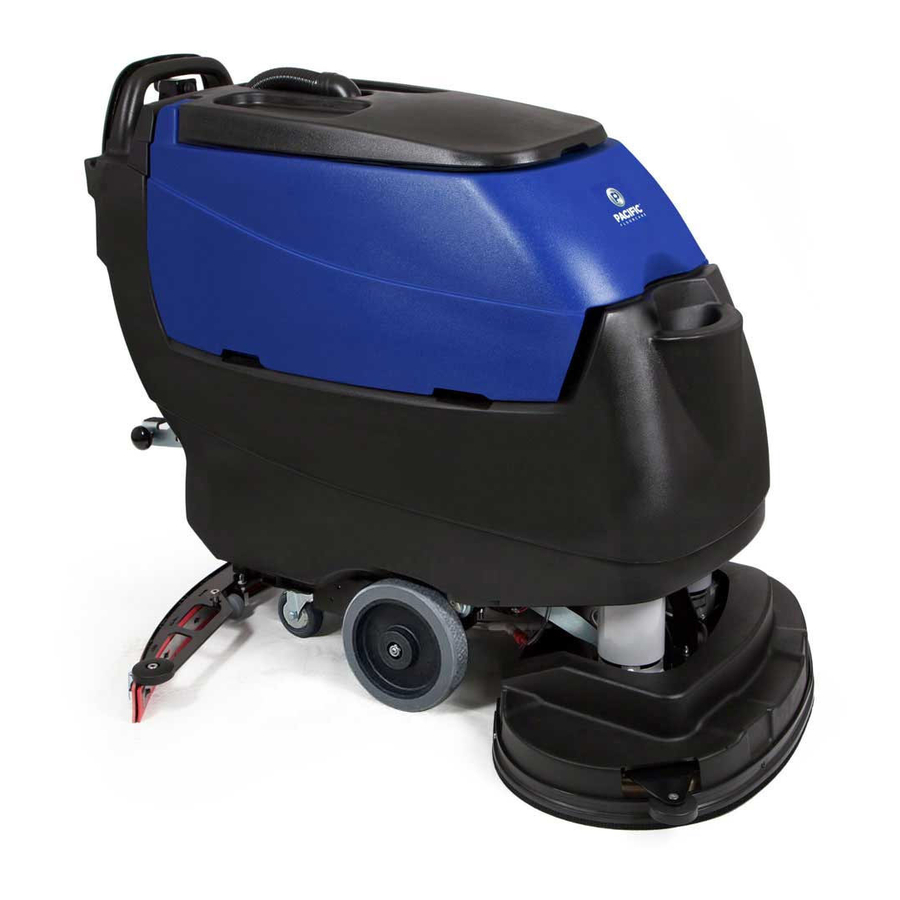
22 gallon mid-size autoscrubber
Hide thumbs
Also See for S-24:
- Operating manual (61 pages) ,
- Manual (92 pages) ,
- Parts & operating manual (69 pages)
Advertisement
Quick Links
22 GALLON MID-SIZE AUTOSCRUBBER
22 GALLON MID-SIZE AUTOSCRUBBER
PARTS & OPERATING MANUAL
PARTS & OPERATING MANUAL
Thank you for purchasing a Pacific Floorcare product. Carefully inspect all components for freight damage.
If such damage is discovered, file a "CONCEALED DAMAGE REPORT" immediately with the delivering
Read this manual carefully and keep it near the machine, protected from liquids and other damaging
substances. Failure to follow the instructions may result in injury or damage to equipment and property.
The contents of this manual are based on the latest product information available at the time of publication.
Pacific Floorcare reserves the right to make changes or improvements without being obliged to apply changes
New manuals can be downloaded from:
S-24 / S-28 / S-32
S-24 / S-28 / S-32
carrier.
to the machines previously sold.
www.pacificfloorcare.com/manuals
Advertisement

Related Manuals for Pacific Floorcare S-24


Summary of Contents for Pacific Floorcare S-24
- Page 1 Failure to follow the instructions may result in injury or damage to equipment and property. The contents of this manual are based on the latest product information available at the time of publication. Pacific Floorcare reserves the right to make changes or improvements without being obliged to apply changes to the machines previously sold.
- Page 2 22 GALLON AUTOSCRUBBER SPECIFICATIONS Features Specifications Model: S-24 (Disk) S-28 (Orbital) Solution Delivery System Solution capacity: 22 gal / 83 l 22 gal / 83 l Solution control: (Standard) 0-.55 gpm / 0-2.1 lpm, Variable knob adjustment 0-.55 gpm / 0-2.1 lpm, Variable knob adjustment Low, Med &...
- Page 3 22 GALLON AUTOSCRUBBER SPECIFICATIONS Features Specifications Model: S-28 (Disk) S-32 (Disk) Solution Delivery System Solution capacity: 22 gal / 83 l 22 gal / 83 l Solution control: (Standard) 0-.55 gpm / 0-2.1 lpm, Variable knob adjustment 0-.55 gpm / 0-2.1 lpm, Variable knob adjustment Low, Med &...
- Page 4 35” SQUEEGEE ASSEMBLY .............................47 40” SQUEEGEE ASSEMBLY .............................48 45” SQUEEGEE ASSEMBLY .............................49 SQUEEGEE LINK...............................50 SCRUB HEADS ................................52 WIRING DIAGRAMS ��������������������������������������������������������������������������������������������������������������������������������������������������������64 S-24 WIRING DIAGRAM ............................64 S-28 (DISK) & S-32 WIRING DIAGRAM .........................66 S-28 ORBITAL WIRING DIAGRAM ........................68 BATTERYSHIELD (OPTIONAL) WIRING DIAGRAM ..................70 ®...
- Page 5 SAFETY INFORMATION This machine is intended for commercial use. Only use recommended pads or brushes and commercially approved floor cleaning chemicals intended for machine application. WARNING: A potentially hazardous situation that, if not avoided, could result in death or serious injury� CAUTION: A potentially hazardous situation that, if not avoided, could result in moderate injury or serious property damage�...
- Page 6 UNPACKING THE MACHINE NOTE: Use a ramp with no more than a 12° incline when loading or unloading the machine. 1. Remove the outer packaging 2. Remove the four cleats and two tie down brackets holding the machine to the pallet 3.
- Page 7 TRANSPORTING THE MACHINE CAUTION: Remove the batteries and get assistance before lifting the machine manually. NOTE: Use a ramp with no more than a 12° incline when loading or unloading the machine. NOTE: Turn power off and put the scrub head in the lowered position during transport. NOTE: Do not rest the orbital head on a hard surface without a pad.
- Page 8 BATTERIES WARNING: Battery posts, terminals, and related accessories contain lead and lead compounds, chemicals known to the State of California to cause cancer and reproductive harm, and during charging, strong inorganic acid mists containing sulfuric acid are involved, a chemical known to the State of California to cause cancer.
- Page 9 SERVICING LEAD ACID BATTERIES (NON-HYDROLINK MODELS) ® WARNING: Battery posts, terminals, and related accessories contain lead and lead compounds, chemicals known to the State of California to cause cancer and reproductive harm, and during charging, strong inorganic acid mists containing sulfuric acid are involved, a chemical known to the State of California to cause cancer.
- Page 10 SERVICING LEAD ACID BATTERIES WITH HYDROLINK ® WATERING SYSTEM WARNING: Battery posts, terminals, and related accessories contain lead and lead compounds, chemicals known to the State of California to cause cancer and reproductive harm, and during charging, strong inorganic acid mists containing sulfuric acid are involved, a chemical known to the State of California to cause cancer.
- Page 11 BATTERYSHIELD AUTOMATED WET BATTERY PROTECTION ® SYSTEM Scrubbers equipped with BatteryShield® technology have a sensor on the battery pack and a red LED indicator on the control panel which monitor and communicate low water conditions. 1. When batteries are fully charged and the key is turned on, BatteryShield will check the water level.
- Page 12 CLEANING THE BATTERYSHIELD SENSOR LIGHT PIPE ® WARNING: Battery posts, terminals, and related accessories contain lead and lead compounds, chemicals known to the State of California to cause cancer and reproductive harm, and during charging, strong inorganic acid mists containing sulfuric acid are involved, a chemical known to the State of California to cause cancer.
- Page 13 CHARGING WARNING: Battery posts, terminals, and related accessories contain lead and lead compounds, chemicals known to the State of California to cause cancer and reproductive harm, and during charging, strong inorganic acid mists containing sulfuric acid are involved, a chemical known to the State of California to cause cancer.
- Page 14 SETTING THE CHARGER ON MACHINES PURCHASED WITHOUT BATTERIES Configure the charging profile to the type of batteries installed on the machine. Switch banks SW1 and SW2 are located behind the label on the lower right corner of the charger next to the green LED. SW2: Set the charge current according to the battery amp hour rate (Reference CHARGE CURRENT AND BATTERY AMP HOURS table below).
- Page 15 OFF-BOARD CHARGER WARNING: Battery posts, terminals, and related accessories contain lead and lead compounds, chemicals known to the State of California to cause cancer and reproductive harm, and during charging, strong inorganic acid mists containing sulfuric acid are involved, a chemical known to the State of California to cause cancer.
- Page 16 PRE-USE SETUP TURNING THE UNIT ON/OFF The key switch is located on the control panel. When the machine is not in use, remove the key and store it in a secure location. CIRCUIT BREAKERS The circuit breakers on the control panel protect the components from high amp-draw. In particular, the scrub head circuit will draw too many amps when overloaded by improper application setup.
- Page 17 DRIVE SYSTEM DRIVE SYSTEM DRIVING OPERATION 1. Bail: Squeezing the Bail activates solution flow, the brush motor, and traction drive. 2. Speed Control: Rotate the Speed Control with either thumb. • Clockwise: Faster • Counter-Clockwise: Slower 3. Reverse Button: Depress Reverse Button and squeeze Bail for reverse operation. SOLUTION DISTRIBUTION SOLUTION DISTRIBUTION FILLING THE SOLUTION TANK...
- Page 18 SOLUTION FLOW: NON-CHEMICAL INJECTION MODELS The Solution Control Knob is located on the top left corner of the control panel. The valve electrically turns on and off with the Scrub Head. The knob controls how much solution passes through the valve when activated. OPTIONAL CHEMICAL INJECTION MODELS 1.
- Page 19 SCRUB DECK SETUP SCRUB DECK SETUP HEAD LIFT • Depress the foot lever (located at the lower right rear corner of the machine) and shift it to the right. • Once clear of the notch, allow the lever to rise while the head lowers into the operating position.
- Page 20 ORBITAL PADS & CHEMICAL-FREE FINISH REMOVAL (CFR) NOTE: Do not lower the orbital head without a pad installed. Doing so may damage the Mighty-Lok face. ® STANDARD CLEANING OPERATIONS 1. Align the corners of the pad to the corners of the aluminum plate and press to attach. 2.
- Page 21 DISK MACHINE PAD DRIVERS & BRUSHES PAD & BRUSH REMOVAL NOTE: Using a pad driver without a pad will damage the floor surface. 1. Toggle the “Brush On/Off” switch to position “A” for 1 second and then immediately to position “B”. The brush will spin in position “A”...
- Page 22 RECOVERY SYSTEM RECOVERY SYSTEM RECOVERY TANK To drain and rinse the recovery tank: 1. Lift the hose off the holder and lower the hose end to the desired drain location. 2. Remove the press-fit cap from the drain hose and squeeze the restriction collar to control the flow. 3.
- Page 23 SQUEEGEE SYSTEM SQUEEGEE ASSEMBLY SETUP Inspect and maintain the squeegee system to achieve peak machine performance. REMOVAL & INSTALLATION • Install: Align the assembly, attach the vacuum hose, and tighten the easy grip knobs. • Remove: Loosen the easy-grip knobs and detach the recovery hose (reverse of installation). SQUEEGEE USE 1.
- Page 24 CLEAN & INSPECT 1. Inspect both squeegee blades. If the blade edges are not clearly defined or are worn halfway through the thickness of the blade, flip the blades to another edge or replace as required. 2. Thoroughly clean and rinse the underside of the squeegee frame, blades and neck.
- Page 25 PAGE INTENTIONALLY BLANK RETURN TO TABLE OF - 21 - CONTENTS...
- Page 26 RECOMMENDED MAINTENANCE SYSTEM REFERENCE SECTION DAILY WEEKLY MONTHLY BIANNUALLY CONTROL PANEL INSPECT ALL CONTROLS AND HARDWARE FOR SECURITY AND SERVICEABILITY PARTS DIAGRAMS VERIFY PROPER OPERATION OF ALL CONTROLS SOLUTION DISTRIBUTION VERIFY SOLUTION FLOWS AND ADJUSTS AS EXPECTED SOLUTION DISTRIBUTION CLEAN AND INSPECT IN-LINE FILTER SOLUTION DISTRIBUTION FLUSH TANK WITH FRESH WATER SOLUTION DISTRIBUTION...
- Page 27 RECOMMENDED SERVICE PARTS (PAGE 1 OF 3) PART NUMBER DESCRIPTION DIAGRAM CATEGORY WEAR ITEM S-24 S-28 DISK S-32 S-28 ORB OPTIONAL 903046 BELT, V-GROOVE, STRETCH SCRUB HEAD 870702 BLADE, FRONT, 35INCH (LINATEX) SQUEEGEE 870708 BLADE, FRONT, 35INCH (URETHANE) SQUEEGEE 870704...
- Page 28 RECOMMENDED SERVICE PARTS (PAGE 2 OF 3) PART NUMBER DESCRIPTION DIAGRAM CATEGORY WEAR ITEM S-24 S-28 DISK S-32 S-28 ORB OPTIONAL 875910 DRIVER, PAD, 16 INCH SCRUB HEAD 873304 FILTER, HEPA, MID RECOVERY TANK 843319 FILTER, SCREEN, BOWL FRAME ASSEMBLY...
- Page 29 RECOMMENDED SERVICE PARTS (PAGE 3 OF 3) PART NUMBER DESCRIPTION DIAGRAM CATEGORY WEAR ITEM S-24 S-28 DISK S-32 S-28 ORB OPTIONAL 555969 PAD 14”X28” TURF CASE 4 SCRUB HEAD 555959 PAD 14”X28” WHITE POLISH CASE 5 SCRUB HEAD 555903 PAD 16” BLACK STRIP CASE 5...
- Page 30 TROUBLESHOOTING GUIDE (PAGE 1 OF 2) ISSUE POTENTIAL CAUSE PROPOSED SOLUTION MANUAL SECTION SOLUTION FLOW SETTING IS TOO LOW ADJUST SOLUTION CONTROL SOLUTION DISTRIBUTION SOLUTION TANK IS EMPTY ADD WATER/SOLUTION TO THE TANK SOLUTION DISTRIBUTION IN-LINE SOLUTION FILTER IS CLOGGED REMOVE AND CLEAN THE FILTER SOLUTION DISTRIBUTION INSUFFICIENT WATER TO...
- Page 31 TROUBLESHOOTING GUIDE (PAGE 2 OF 2) ISSUE POTENTIAL CAUSE PROPOSED SOLUTION MANUAL SECTION SCRUB HEAD IS STILL RAISED LOWER SCRUB HEAD SCRUB DECK SETUP BATTERYSHIELD® LED IS ILLUMINATED AND HAS SERVICE THE BATTERIES BATTERIES DISABLED THE SCRUB HEAD (IF EQUIPPED) BATTERIES ARE DISCHARGED BELOW THRESHOLD CHARGE BATTERIES CHARGING...
- Page 32 PARTS DIAGRAMS BATTERIES, BATTERYSHIELD BATTERIES, BATTERYSHIELD & HYDROLINK & HYDROLINK ® ® ® ® ITEM PART NUMBER DESCRIPTION COMES WITH 4 MANIFOLDS (BATT CAPS), SERVICING 871301 BATTERY, 6V, 260AH, LA TUBE (NOT PICTURED), AND HAND PUMP 871302 BATTERY, 6V, 250AH, MF (NOT SHOWN, OPTIONAL) 858202 FOAM, SPACER, BATTERY 911640...
- Page 33 OPTIONAL ONBOARD CHARGER OPTIONAL ONBOARD CHARGER ITEM PART NUMBER DESCRIPTION 852407 CHARGER, 24V, ONBRD, CULUS 850805 BRACKET, MTG, CORD 870817 BRACKET, MTG, CHARGER 962186 SCREW, PAN, #10-32 X 1.0, SS W401D WASHER, FLAT, #10 920666 NUT, NYLOCK, #10-32, SS W104D WASHER, FLAT, .25 980002 WASHER, LOCK, SPLIT, .25...
- Page 34 CONTROLS S-24 DISK CONTROLS (SEE ADDITIONAL DIAGRAM FOR MODELS EQUIPPED WITH BATTERYSHIELD OR CHEMICAL INJECTION) ® RETURN TO TABLE OF CONTENTS...
- Page 35 S-24 DISK CONTROLS (SEE ADDITIONAL DIAGRAM FOR MODELS EQUIPPED WITH BATTERYSHIELD OR CHEMICAL INJECTION) ® ITEM QTY PART NUMBER DESCRIPTION ITEM QTY PART NUMBER DESCRIPTION 4 855601 MOUNT, BEARING, PLASTIC 2 962455 SCREW, TRUSS, .25-20 X 1.0 1 877101 PANEL, CONTROLS 2 W132D SCREW, PAN, #6-32 X 1.0, ZINC...
- Page 36 S-28 & S-32 DISK CONTROLS (SEE ADDITIONAL DIAGRAM FOR MODELS EQUIPPED WITH BATTERYSHIELD OR CHEMICAL INJECTION) ® RETURN TO TABLE OF CONTENTS...
- Page 37 S-28 & S-32 DISK CONTROLS (SEE ADDITIONAL DIAGRAM FOR MODELS EQUIPPED WITH BATTERYSHIELD OR CHEMICAL INJECTION) ® ITEM QTY PART NUMBER DESCRIPTION ITEM QTY PART NUMBER DESCRIPTION 4 855601 MOUNT, BEARING, PLASTIC 2 962455 SCREW, TRUSS, .25-20 X 1.0 1 877101 PANEL, CONTROLS 2 W132D SCREW, PAN, #6-32 X 1.0, ZINC...
- Page 38 S-28 ORBITAL CONTROLS (SEE ADDITIONAL DIAGRAM FOR MODELS EQUIPPED WITH BATTERYSHIELD OR CHEMICAL INJECTION) ® RETURN TO TABLE OF CONTENTS...
- Page 39 S-28 ORBITAL CONTROLS (SEE ADDITIONAL DIAGRAM FOR MODELS EQUIPPED WITH BATTERYSHIELD OR CHEMICAL INJECTION) ® ITEM QTY PART NUMBER DESCRIPTION ITEM QTY PART NUMBER DESCRIPTION 4 855601 MOUNT, BEARING, PLASTIC 1 920013 NUT, #10-32, ZINC 1 877101 PANEL, CONTROLS 1 850806 BRACKET, PLUG 3 911646 SWITCH, SNAP, WITH ROLLER...
- Page 40 OPTIONAL BATTERYSHIELD & CHEMICAL INJECTION CONTROLS ITEM PART NUMBER DESCRIPTION 872401 CONTROLLER, DISPENSING 875001 KNOB, .25 BORE, SMALL 875104 LABEL, CONTROL, SOLUTION 875107 LED, RED, 24VDC 855115 LABEL BATTERYSHIELD WITH QR CODE 911684 HARNESS, BATTERYSHIELD 911680 HARNESS, SOLUTION CONTROL 855012 KEY REPLMNT SCRUB 2-SET FOR 911647 RETURN TO TABLE OF...
- Page 41 ELECTRONICS S-24 ELECTRONICS (SEE ADDITIONAL DIAGRAM FOR MODELS EQUIPPED WITH BATTERYSHIELD OR CHEMICAL INJECTION) ® ITEM PART NUMBER DESCRIPTION 879101 CONTROLLER, I-DRIVE, MID 879801 PANEL, ELECTRONICS 912402 CONTACTOR, 24VDC, 70A 912401 CONTACTOR, 24V, 100A 858501 STAND-OFF, INSULATED, .25-20 W104D WASHER, FLAT, .25 980002 WASHER, LOCK, SPLIT, .25...
- Page 42 S-28 & S-32 DISK ELECTRONICS (SEE ADDITIONAL DIAGRAM FOR MODELS EQUIPPED WITH BATTERYSHIELD OR CHEMICAL INJECTION) ® ITEM PART NUMBER DESCRIPTION 879101 CONTROLLER, I-DRIVE, MID 879801 PANEL, ELECTRONICS 912402 CONTACTOR, 24VDC, 70A 912401 CONTACTOR, 24V, 100A 858501 STAND-OFF, INSULATED, .25-20 W104D WASHER, FLAT, .25 980002...
- Page 43 S-28 ORBITAL ELECTRONICS (SEE ADDITIONAL DIAGRAM FOR MODELS EQUIPPED WITH BATTERYSHIELD OR CHEMICAL INJECTION) ® ITEM PART NUMBER DESCRIPTION 879101 CONTROLLER, I-DRIVE, MID 879801 PANEL, ELECTRONICS 912402 CONTACTOR, 24VDC, 70A 912401 CONTACTOR, 24V, 100A 858501 STAND-OFF, INSULATED, .25-20 W104D WASHER, FLAT, .25 980002 WASHER, LOCK, SPLIT, .25 W169D...
- Page 44 OPTIONAL BATTERSHIELD ELECTRONICS ® ITEM PART NUMBER DESCRIPTION 980025 WASHER, SPLIT LOCK, #6, ZINC 911685 RELAY, 24VDC, BATTERYSHIELD W315D SCREW, PAN, #6-32 X .50, BLK 980033 WASHER, FLAT, #6, SS RETURN TO TABLE OF CONTENTS...
- Page 45 FRAME ASSEMBLY ITEM PART NUMBER DESCRIPTION 873201 FRAME, SCRUBBER, 20 TRACT W243D WASHER, FLAT, 5/16, SS 980094 WASHER, SPLIT LOCK, .31, SS 962269 SCREW, HEX, .31-18 X .75, SS 855014 KIT VALVE SCRUBBER REPLMNT 859402 VALVE SOLENOID 24V NONADJ 14 W189D SCREW, HEX, 1/4-20 X .75, SS, PATCH 980029 WASHER, LOCK, STAR, EXTERNAL...
- Page 46 HEAD LIFT ASSEMBLY ITEM QTY PART NUMBER DESCRIPTION 1 870801 BRACKET, LIFT, HEAD 6 875601 MOUNT, BEARING, PLASTIC 1 875106 LEVER, DOWNPRESSURE 1 875105 LABEL, FOOT, GRIP, LARGE 1 980108 WASHER, FLAT, .31ID, 1.25OD, .12THK, SS 1 980094 WASHER, SPLIT LOCK, .31, SS 1 962279 SCREW, SOCKET CAP, .31X1.0, SS 4 980612...
- Page 47 SOLUTION TANK ITEM QTY PART NUMBER DESCRIPTION 1 878601 TANK, SOLUTION, 22 GAL 1 870805 BRACKET, SUPPORT, LEVER 1 879004 TUBE, SIGHT, REPLACEMENT 2 853303 FITTING, STR, BM12, PM08 1 W189D SCREW, HEX, 1/4-20 X .75, SS, PATCH 1 920037 NUT, THIN JAM, 1/4-20, ZINC 1 962455 SCREW, TRUSS, .25-20 X 1.0...
- Page 48 RECOVERY TANK AND VACUUM AVAILABLE VACUUM MOTOR KIT - #875023 ITEM DESCRIPTION ITEM PART NUMBER DESCRIPTION ITEM PART NUMBER DESCRIPTION 877802 SHEET INSTR MID-SCRUBBER VAC MTR REPL 223370 FLOAT, SHUTOFF 980094 WASHER, SPLIT LOCK, .31, SS 873314 GASKET, FOAM, VACUUM 853304 FITTING, STR, BM24, PM20 875110...
- Page 49 PAGE INTENTIONALLY BLANK RETURN TO TABLE OF CONTENTS...
- Page 50 OPTIONAL CHEMICAL INJECTION ITEM PART NUMBER DESCRIPTION 877002 PUMP, 24VDC, SOLENOID, EMX08 870810 BRACKET, HEAT SINK 870811 BRACKET, MTG, HEAT SINK S764P2 FILTER, STRAINER 871501 CAP, 38MM, WITH HOLE 879402 VALVE, CHECK, .188 X .50 BARB 873308 FITTING, TEE, 0.50 INCH 853301 FITTING, REDUCER, BM08, BM04 980002...
- Page 51 35” SQUEEGEE ASSEMBLY LINATEX: 878526 URETHANE: 878511 ITEM PART NUMBER DESCRIPTION 873203 FRAME, SQUEEGEE, 35 INCH 870701 BLADE, REAR, 35INCH (LINATEX) 870707 BLADE, REAR, 35INCH (URETHANE) 870702 BLADE, FRONT, 35INCH (LINATEX) 870708 BLADE, FRONT, 35INCH (URETHANE) 877203 RETAINER, REAR, 35 INCH 877204 RETAINER, FRONT, 35 INCH 859703...
- Page 52 40” SQUEEGEE ASSEMBLY LINATEX: 878527 URETHANE: 878512 ITEM PART NUMBER DESCRIPTION 873204 FRAME, SQUEEGEE, 40 INCH 870703 BLADE, REAR, 40INCH (LINATEX) 870709 BLADE, REAR, 40INCH (URETHANE) 870704 BLADE, FRONT, 40INCH (LINATEX) 870710 BLADE, FRONT, 40INCH (URETHANE) 877201 RETAINER, REAR, 40 INCH 877202 RETAINER, FRONT, 40 INCH 859703...
- Page 53 45” SQUEEGEE ASSEMBLY LINATEX: 878528 URETHANE: 878513 ITEM PART NUMBER DESCRIPTION 873205 FRAME SQUEEGEE 45 INCH 870705 BLADE REAR 45 INCH LINATEX 870711 BLADE REAR 45 INCH URETHANE 870706 BLADE FRONT 45 INCH LINARD 870712 BLADE FRONT 45 INCH URETHANE 877205 RETAINER, REAR, 45 INCH 877206...
- Page 54 SQUEEGEE LINK ITEM PART NUMBER DESCRIPTION 849709 WHEEL, 2 OD, .31 ID 962464 SCREW, BUTTON, .31-18 X 1.25, ZINC 850501 AXLE, WHEEL, SQUEEGEE 902051 BEARING, ROD END, .38 FEM 870802 BRACKET, LINK, SQUEEGEE 980105 WASHER, PLASTIC, THRUST 920035 NUT, NYLOCK, .38-16, SS 962075 SCREW, HEX, 3/8-16 X 1.5, SS 962028...
- Page 55 PAGE INTENTIONALLY BLANK RETURN TO TABLE OF CONTENTS...
- Page 56 SCRUB HEADS S-24 SCRUB HEAD (PAGE 2 OF 2) ITEM PART NUMBER DESCRIPTION 870902 BRUSH, POLY, 12 INCH 870908 BRUSH, NYLON, 12 INCH 870909 BRUSH, GRIT, 12 INCH 859703 WHEEL, GUIDE 875019 KIT SKIRT REPLACEMENT (ITEMS 6 - 10) 962263 SCREW, BUTT, SOCK, .25-20X.62, SS BO...
- Page 57 S-24 SCRUB HEAD (PAGE 1 OF 2) ITEM PART NUMBER DESCRIPTION ITEM PART NUMBER DESCRIPTION 876602 PLATE, MTG, 24 INCH 920039 NUT, .62-18, NYLOCK, LOW 858203 SPACER, WHEEL, GUIDE 870814 BRACKET, SUPPORT, 24XM 920035 NUT, NYLOCK, .38-16, SS W104D WASHER, FLAT, .25...
- Page 58 S-28 DISK SCRUB HEAD *** PRIOR TO SERIAL NUMBER 121567 *** RETURN TO TABLE OF CONTENTS...
- Page 59 S-28 DISK SCRUB HEAD *** PRIOR TO SERIAL NUMBER 121567 *** ITEM QTY PART NUMBER DESCRIPTION ITEM QTY PART NUMBER DESCRIPTION 870901 BRUSH, POLY, 14 INCH 1 876601 PLATE, MTG, 28INCH 870904 BRUSH, NYLON, 14 INCH 1 873802 GUIDE, DRIVER, RH 870906 BRUSH, GRIT, 14 INCH 1 204179 - 15.2”...
- Page 60 S-28 DISK SCRUB HEAD *** AFTER SERIAL NUMBER 121567 *** RETURN TO TABLE OF CONTENTS...
- Page 61 S-28 DISK SCRUB HEAD *** AFTER SERIAL NUMBER 121567 *** ITEM QTY PART NUMBER DESCRIPTION ITEM QTY PART NUMBER DESCRIPTION 1 876612 PLATE, MTG, 28INCH, TORNADO 4 962263 SCREW, BUTT, SOCK, .25-20X.62, SS BO 1 855022 KIT WHEEL GUIDE REPLACEMENT 4 920665 NUT, NYLOCK, 1/4-20, SS 2 875203...
- Page 62 S-32 SCRUB HEAD *** PRIOR TO SERIAL NUMBER 121567 *** RETURN TO TABLE OF CONTENTS...
- Page 63 S-32 SCRUB HEAD *** PRIOR TO SERIAL NUMBER 121567 *** ITEM QTY PART NUMBER DESCRIPTION ITEM QTY PART NUMBER DESCRIPTION 855022 KIT GUIDE WHEEL RELACEMENT ANTI-RATTLE 876603 PLATE, MTG, 32INCH 915008 KEY, SQUARE, 5MM X 5 X 40MM 204179 - 17.2” TUBING, 1/4”...
- Page 64 S-32 SCRUB HEAD *** AFTER SERIAL NUMBER 121567 *** RETURN TO TABLE OF CONTENTS...
- Page 65 S-32 SCRUB HEAD *** AFTER SERIAL NUMBER 121567 *** ITEM QTY PART NUMBER DESCRIPTION ITEM QTY PART NUMBER DESCRIPTION 1 876613 PLATE, MTG, 32INCH, RIGID 2 853301 FITTING, REDUCER, BM08, BM04 1 855022 KIT GUIDE WHEEL REPL ANTI-RATTLE 2 224130 - 1.75” TUBING, 1/2” 1 870804 BRACKET, SUPPORT, HEAD 1 873308...
- Page 66 S-28 ORBITAL SCRUB HEAD (PAGE 1 OF 2) ITEM PART NUMBER DESCRIPTION 870812 BRACKET, MTG, HEAD, ORBITAL 855022 KIT GUIDE WHEEL REPLACEMENT ANTI-RATTLE 876609 PLATE, MOUNTING, MOTOR 858203 SPACER, WHEEL, GUIDE W243D WASHER, FLAT, 5/16, SS 964009 SCREW, SCK, FLT, M6-1 X 20, SS, PATCH 852003 CLAMP, P-SHAPED, .62 DIA 962263...
- Page 67 S-28 ORBITAL SCRUB HEAD (PAGE 2 OF 2) AVAILABLE PADS AVAILABLE HEAD REBUILD KIT - #875022 ITEM PART NUMBER DESCRIPTION Item Item Description 875009 KIT, PLATE, REPL, ORBIT PART NUMBER DESCRIPTION 876607 PLATE, ORBITAL, 28 INCH 877801 INSTRUCTION BOOKLET 555909 PAD 14”X28”...
- Page 68 WIRING DIAGRAMS S-24 WIRING DIAGRAM ***ALL SERIAL NUMBERS*** TROUBLESHOOTING TIPS: 1. If the scrub head is not working when lowered, be aware that BatteryShield ® intentionally disables the scrub head when the batteries need water. Refer to the BATTERYSHIELD ®...
- Page 69 PAGE INTENTIONALLY BLANK RETURN TO TABLE OF CONTENTS...
- Page 70 S-28 (DISK) & S-32 WIRING DIAGRAM ***AFTER SERIAL NUMBER 113191*** TROUBLESHOOTING TIPS 1. If the scrub head is not working when lowered, be aware that BatteryShield ® intentionally disables the scrub head when the batteries need water. Refer to the BATTERYSHIELD ®...
- Page 71 S-28 (DISK) & S-32 WIRING DIAGRAM ***PRIOR TO SERIAL NUMBER 113191*** TROUBLESHOOTING TIPS: 1. If the scrub head is not working when lowered, be aware that BatteryShield ® intentionally disables the scrub head when the batteries need water. Refer to the BATTERYSHIELD ®...
- Page 72 S-28 ORBITAL WIRING DIAGRAM ***PRIOR TO SERIAL NUMBER 113191*** TROUBLESHOOTING TIPS 1. If the scrub head is not working when lowered, be aware that BatteryShield ® intentionally disables the scrub head when the batteries need water. Refer to the BATTERYSHIELD ®...
- Page 73 S-28 ORBITAL WIRING DIAGRAM ***AFTER SERIAL NUMBER 113191*** TROUBLESHOOTING TIPS 1. If the scrub head is not working when lowered, be aware that BatteryShield ® intentionally disables the scrub head when the batteries need water. Refer to the BATTERYSHIELD ® AUTOMATIC WET BATTERY PROTECTION SYSTEM section of this manual.
- Page 74 BATTERYSHIELD (OPTIONAL) WIRING DIAGRAM ® NOTE: BatteryShield intentionally interrupts the scrub head circuit when the batteries need water. Refer to the BATTERYSHIELD ® ® AUTOMATIC WET BATTERY PROTECTION SYSTEM section of this manual. BATTERYSHIELD® SENSOR IS MATED AND CALIBRATED TO THE MANIFOLD (BATT CAP) FROM THE FACTORY.
- Page 75 OPTIONAL CHEMICAL INJECTION WIRING DIAGRAM RETURN TO TABLE OF CONTENTS...
- Page 76 DATE MAINTENANCE LOG RETURN TO TABLE OF - 72 - CONTENTS...
- Page 77 DATE MAINTENANCE LOG RETURN TO TABLE OF - 73 - CONTENTS...
- Page 78 PAGE INTENTIONALLY BLANK RETURN TO TABLE OF - 74 - CONTENTS...
- Page 79 REVISION REVISION LOG 2019.10.24 UPDATED BALLOONS FOR THE RECOVERY TANK, PAGE 37. 2020.03.02 MULTIPLE UPDATES, MISC CORRECTIONS AND ADDITIONS. 2020.06.15 UPDATE SQUEEGEE ASSEMBLY IMAGES, PAGES 45-47. 2020.7.29 UPDATE WARRANTY INFORMATION. 2020.10.16 UPDATE WATERING LEAD ACID BATTERIES WITH HYDROLINK, PAGE 9. 2021.1.5 UPDATE BATTERYSHIELD WARRANTY POLICY 2021.2.2...
- Page 80 www.pacificfloorcare.com...
Need help?
Do you have a question about the S-24 and is the answer not in the manual?
Questions and answers