Table of Contents
Advertisement
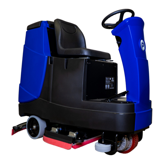
RS28
30 GALLON RIDER AUTO SCRUBBER
PARTS & OPERATING MANUAL
Thank you for purchasing a Pacific Floorcare product. Carefully inspect all components for freight damage. If such
damage is discovered, file a "CONCEALED DAMAGE REPORT" immediately with the delivering carrier.
Read this manual carefully and keep it near the machine, protected from liquids and other damaging substances. Failure to
follow the instructions may result in injury or damage to equipment and property.
The contents of this manual are based on the latest product information available at the time of publication. Pacific
Floorcare reserves the right to make changes or improvements without being obliged to apply changes to the machines
previously sold.
New manuals can be downloaded from:
www.pacificfloorcare.com/manuals
Advertisement
Table of Contents

Related Manuals for Pacific Floorcare RS28


Summary of Contents for Pacific Floorcare RS28
- Page 1 30 GALLON RIDER AUTO SCRUBBER PARTS & OPERATING MANUAL Thank you for purchasing a Pacific Floorcare product. Carefully inspect all components for freight damage. If such damage is discovered, file a “CONCEALED DAMAGE REPORT” immediately with the delivering carrier. Read this manual carefully and keep it near the machine, protected from liquids and other damaging substances. Failure to follow the instructions may result in injury or damage to equipment and property.
- Page 2 30 GALLON RIDER AUTO SCRUBBER SPECIFICATIONS Features Specifications Model RS28 (Disk) RS28 (Orbital) Machine Specifications Length 60 in (152.4 cm) 60 in (152.4 cm) Width (w/o Squeegee) 27 in (68.6 cm) 27 in (68.6 cm) Height 52 in (132.1 cm) 52 in (132.1 cm)
-
Page 3: Table Of Contents
TABLE OF CONTENTS SAFETY INFORMATION ���������������������������������������������������������������������������������������������������������������������������������������������������1 UNPACKING THE MACHINE �������������������������������������������������������������������������������������������������������������������������������������������3 TRANSPORTING THE MACHINE �����������������������������������������������������������������������������������������������������������������������������������3 BATTERIES ���������������������������������������������������������������������������������������������������������������������������������������������������������������������������4 SERVICING LEAD ACID BATTERIES (NON-HYDROLINK MODELS) ..............5 ® SERVICING LEAD ACID BATTERIES WITH HYDROLINK WATERING SYSTEM ...........6 ® BATTERYSHIELD AUTOMATED WET BATTERY PROTECTION SYSTEM............6 ®... -
Page 4: Safety Information
SAFETY INFORMATION WARNING: A potentially hazardous situation that, if not avoided, could result in death or serious injury� CAUTION: A potentially hazardous situation that, if not avoided, could result in moderate injury or serious property damage� NOTE: Information that will prevent premature equipment failure or minor property damage� WARNING: This product can expose you to chemicals including lead and lead compounds which are known to the State of California to cause cancer and birth defects or other reproductive harm. - Page 5 SAFETY INFORMATION CONTINUED CAUTION: Keep hands away from spinning brushes. CAUTION: Do not modify the machine from its original design. CAUTION: Wear non-slip shoes when operating machine. CAUTION: Reduce speed when turning or operating on inclines and slippery surfaces. CAUTION: Use Bromine only in your tank treatment system! Do not use chlorine.
-
Page 6: Unpacking The Machine
UNPACKING THE MACHINE Remove outer cardboard packaging. Remove the shrink wrap securing the ramp and allow the ramp (not shown) to lower to the ground. Using a #2 Philips driver, remove the screws from the front and rear wood wheel chocks. Using a 3/8”... -
Page 7: Batteries
BATTERIES WARNING: Battery posts, terminals, and related accessories contain lead and lead compounds, chemicals known to the State of California to cause cancer and reproductive harm, and during charging, strong inorganic acid mists containing sulfuric acid are involved, a chemical known to the State of California to cause cancer. Wash hands after handling. For more information go to www.P65Warnings.ca.gov. -
Page 8: Servicing Lead Acid Batteries (Non-Hydrolink ® Models)
SERVICING LEAD ACID BATTERIES (NON-HYDROLINK MODELS) ® REQUIRED EQUIPMENT • Eye protection • Acid resistant gloves • Distilled water • Baking soda to neutralize acid spills SAFETY NEVER: • Add acid to a battery. • Smoke near batteries. • Charge a frozen battery. •... -
Page 9: Servicing Lead Acid Batteries With Hydrolink ® Watering System
SERVICING LEAD ACID BATTERIES WITH HYDROLINK WATERING ® SYSTEM Position the container of distilled water below the level of the top of the batteries to prevent siphoning. Place the end of the watering system hose in the distilled water and squeeze the bulb to fill the system. Remove the dust cover from the Hydrolink snake connected to the batteries. -
Page 10: Cleaning The Batteryshield ® Sensor Light Pipe
CLEANING THE BATTERYSHIELD SENSOR LIGHT PIPE ® CAUTION: Always wear protective clothing, gloves and goggles when handling and charging batteries. NOTE: All repairs must be performed by a qualified service technician using approved replacement parts. Locate and remove the battery cap with the BatteryShield sensor module. -
Page 11: Charging
CHARGING WARNING: Batteries emit hydrogen and oxygen gas. • Keep sparks and open flame away. • Do not smoke near the machine. • Charge batteries in a well-ventilated area with the battery compartment open. WARNING: Do not wear jewelry when working near moving or electrical components. WARNING: Do not plug in the charger cable if wall cord or battery harness is damaged. -
Page 12: Operation
OPERATION MACHINE OVERVIEW A. SEAT ASSEMBLY P. CHARGER STATUS VIEW WINDOW B. STEERING WHEEL Q. SEAT ADJUSTMENT C. STEERING WHEEL ADJUSTMENT R. HOUR METER & (OPTIONAL) LAMP SWITCH D. CONTROL PANEL S. SQUEEGEE HOSE E. KEY SWITCH T. RECOVERY VACUUM MOTOR & HEPA FILTER (LOCATED BEHIND COVER) F. -
Page 13: Control Panel
CONTROL PANEL Zone 1: Modes of Operation • SCRUB ONLY: Allows the operator to run the scrub head only. • VACUUM ONLY: Allows the operator to run the squeegee/vacuum system only. • VACUUM + SCRUB: Allows the operator to run both the scrub head and squeegee/vacuum systems. Zone 2: Operational Settings •... -
Page 14: Machine Error Codes
MACHINE ERROR CODES The battery needs charging or there is a bad connection to the battery. Check the connections to the battery. If the connections are good, try charging the battery. There is a bad connection to the Traction motor. Check all connections between the motor and the control system. There is a bad connection to the Brush motor/motors. -
Page 15: Drive System
DRIVE SYSTEM Turn the machine on using the key switch located on the right side of the steering column. Set the desired maximum speed using the MAX SPEED selector on the Control Panel Select the desired direction of travel using the FORWARD and REVERSE selectors on the Control Panel. Maintain control of the Steering Wheel at all times during operation. - Page 16 CHEMICAL INJECTION For machines equipped with the optional chemical injection system: Place a 1-gallon chemical container in the holder (located behind the battery compartment, under the Recovery Tank). Insert the hose into the container so that the filter at the end of the hose rests on the bottom of the container.
-
Page 17: Scrub Head
SCRUB HEAD Running the machine in SCRUB ONLY or VACUUM+SCRUB will lower the scrub head to the floor. The scrub head motors will begin running when the throttle pedal is depressed. Scrub head down pressure is set using the DOWN PRESSURE selector on the Control Panel. -
Page 18: Disk Scrub Head
DISK SCRUB HEAD STANDARD OPERATION NOTE: Do not operate the Disk Scrub Head without a pad installed on the pad driver. Operating the head without a pad will damage the floor. With power off and the Scrub Head raised, lift the Side Squeegees to the raised position. Align the pad driver assemblies with the bayonet drivers on the machine. -
Page 19: Recovery System
RECOVERY SYSTEM RECOVERY TANK To drain and rinse the recovery tank: Remove the Recovery Drain Hose from the holder and lower the end into the drain location. Remove the press-fit cap from the Recovery Drain Hose, squeezing the restriction collar to control the flow. As the tank drains, lean the Recovery Tank back and open the lid. - Page 20 SQUEEGEE SYSTEM Squeegee Blades and system should be inspected and maintained regularly to achieve peak machine performance. REMOVAL & INSTALLATION Install: Align the slots in the squeegee assembly with the easy-grip knobs, attach the vacuum hose, and tighten the knobs. Remove: Loosen the easy-grip knobs, remove the vacuum hose, and remove the assembly.
- Page 21 INSPECTION & CLEANING Inspect both squeegee blades. Blades edges are considered worn if the edge is not clearly defined or if the edge is worn halfway through the thickness of the blade. Blades can be flipped and rotated to use all four edges. Thoroughly clean the blades, frame, and neck of any debris.
-
Page 22: Recommended Maintenance
RECOMMENDED MAINTENANCE SYSTEM DAILY WEEKLY MONTHLY BIANUALLY CONTROL PANEL/STEERING INSPECT ALL CONTROLS AND HARDWARE FOR SECURITY & SERVICEABILITY VERIFY THROTTLE PEDAL FUNCTION VERIFY PROPER OPERATION OF ALL CONTROLS VERIFY FUNCTION OF STEERING SYSTEM INSPECT AND LUBRICATE U-JOINT SOLUTION DISTRIBUTION VERIFY SOLUTION FLOW & ADJUSTMENT OPERATION CLEAN &... - Page 23 PAGE INTENTIONALLY LEFT BLANK RETURN TO TABLE OF - 20 - CONTENTS...
-
Page 24: Recommended Service Parts
RECOMMENDED SERVICE PARTS PART NUMBER DESCRIPTION MACHINE SUB-SYSTEM WEAR ITEM RS28 (DISK) RS28 (ORBITAL) OPTIONAL 857003 PUMP ASSY, HND, HYDROLINK BATTERY/BATTERY CHARGING 911758 FUSE MIDI BOLT-DOWN 100A 32V ELECTRICAL 549701 WHEEL 5X2 BALL BEARING FRAME ASSEMBLY 871501 CAP, 38MM, W/ HOLE... - Page 25 RECOMMENDED SERVICE PARTS PART NUMBER DESCRIPTION MACHINE SUB-SYSTEM WEAR ITEM RS28 (DISK) RS28 (ORBITAL) OPTIONAL 890706 BLADE REAR 33 INCH URETHANE SQUEEGEE 890705 BLADE FRONT 33 INCH URETHANE SQUEEGEE 890703 BLADE REAR 33 INCH LINATEX SQUEEGEE 890704 BLADE FRONT 33 INCH LINARD...
-
Page 26: Troubleshooting Guide
TROUBLESHOOTING GUIDE ISSUE POTENTIAL CAUSE PROPOSED SOLUTION SOLUTION FLOW SETTING IS TOO LOW ADJUST SOLUTION CONTROL SOLUTION TANK IS EMPTY ADD WATER/SOLUTION TO THE TANK IN-LINE SOLUTION FILTER IS CLOGGED REMOVE AND CLEAN THE FILTER SOLUTION TUBE IS CLOGGED, KINKED, OR DAMAGED INSPECT TUBES SOLUTION SHUT OFF VALVE IS CLOSED OPEN VALVE... - Page 27 TROUBLESHOOTING GUIDE ISSUE POTENTIAL CAUSE PROPOSED SOLUTION STILL IN DELAY MODE ALLOW 30-45 SECONDS FOR VACUUM TO SHUT DOWN VACUUM MOTOR WILL NOT TURN OFF FAULTY MAIN CONTROLLER INSPECT AND REPLACE AS REQUIRED SCRUB HEAD IS STILL RAISED LOWER SCRUB HEAD BATTERYSHIELD®...
-
Page 28: Parts Diagrams
PARTS DIAGRAMS FRAME ASSEMBLY Page 1 of 3 ITEM PART NUMBER DESCRIPTION 895601 MOUNT WIRE-TIE PRESS IN 893801 GROMMET PUSH-IN FOR 1.5INCH 962269 SCREW, HEX, .31-18 X .75, SS 980094 WASHER, SPLIT LOCK, .31, SS 890802 BRACKET GUIDE HEAD 893202 FRAME WELDMENT RIDER 962296 SCREW BUTTON .31-18 X 3.50 SS... - Page 29 FRAME ASSEMBLY Page 2 of 3 ITEM PART NUMBER DESCRIPTION 911734 HARNESS DRIVE FLEXIBLE W FITTING 964257 SCREW SOCKET HEAD CAP M8 X 80 980094 WASHER, SPLIT LOCK, .31, SS 964449 SCREW M8X25 FLAT PATCH 896104 PLATE TOP STEER MANUAL 852003 CLAMP, P-SHAPED, .62 DIA 964448...
- Page 30 FRAME ASSEMBLY Page 3 of 3 ITEM PART NUMBER DESCRIPTION 853301 FITTING, REDUCER, BM08, BM04 224130 TUBING 1/2” S453P CLAMP, HOSE, WORM 897006 PUMP SOLUTION 24VDC 843319 FILTER, SCREEN, BOWL W169D SCREW, HEX, .25-20 X .50 890820 BRACKET MOUNTING VALVE 980002 WASHER, LOCK, SPLIT, .25 859402...
-
Page 31: Solution Tank
SOLUTION TANK ITEM PART NUMBER DESCRIPTION 898602 TANK SOLUTION RIDER 895109 LABEL INFORMATION RIDER 897002 PANEL COVER ACTUATOR 962263 SCREW, BUTT, SOCK, .25-20X.62, SS BO 895114 LABEL GRIP FOOT 897004 PEDAL ASSY LOW PROFILE 896101 PLATE FOOT RIDER 894205 HOUSING DEBRIS PEDAL 893801 GROMMET PUSH-IN FOR 1.5INCH 893302... -
Page 32: Steering Column
STEERING COLUMN Page 1 of 2 ITEM PART NUMBER DESCRIPTION 895117 LABEL STEERING WHEEL PACIFIC W502D NUT, NYLOCK, .5-13, THIN, ZINC W120D WASHER FLAT .56X1.38 899703 WHEEL STEERING 12INCH RIDER 980027 WASHER FLAT .765 ID 1.312 OD PLASTIC 915007 KEY, WOODRUFF, 5MM 898306 SPRING COMPRESSION 2.5L .98OD 891311... - Page 33 STEERING COLUMN Page 2 of 2 ITEM PART NUMBER DESCRIPTION 896806 PLUG HOLE PLASTIC .375 INCH 895110 LABEL COVER BATTERYSHIELD 962263 SCREW, BUTT, SOCK, .25-20X.62, SS BO 895101 LABEL CONTROL RIDER 897001 PANEL CONTROL OPERATOR 911621 METER, BATTERY 920034 NUT, NYLOCK, #6-32, SS 878208 SPACER PLASTIC #10 X .25 THICK 892403...
-
Page 34: Recovery System
RECOVERY SYSTEM Page 1 of 2 ITEM PART NUMBER DESCRIPTION 853304 FITTING, STR, BM24, PM20 856803 PLUG HOLE 1 INCH BLACK 892303 COVER RECOVERY RIDER 962462 SCREW, SHOULDER, .38 X 1.75, SS 879202 TRAY, PUCK 879201 TRAY, DEBRIS 875110 LABEL, INSTRUCT, BROMINE 898601 TANK RECOVERY RIDER 853308... - Page 35 RECOVERY SYSTEM Page 2 of 2 ITEM PART NUMBER DESCRIPTION 875202 MOTOR, VAC, 24VDC, PERIP 852101 CLAMP, WIRE, P-SHAPED 894101 HOSE SQUEEGEE RIDER STRAIGHT CUFF 873304 FILTER, HEPA, MID 962269 SCREW, HEX, .31-18 X .75, SS 980094 WASHER, SPLIT LOCK, .31, SS W243D WASHER, FLAT, 5/16, SS 892001...
-
Page 36: Head Lift
HEAD LIFT Page 1 of 2 ITEM PART NUMBER DESCRIPTION 920036 NUT, NYLOCK, 5/16-18, SS W243D WASHER, FLAT, 5/16, SS 902057 BEARING 2-BOLT FLANGE 1INCH 962269 SCREW, HEX, .31-18 X .75, SS 897703 SHAFT LIFT HEAD RIDER 980612 WASHER, NYL, .50 X 1.25 X .062 980093 WASHER, WAVE, .50INCH 962465... - Page 37 HEAD LIFT Page 2 of 2 ITEM PART NUMBER DESCRIPTION 892402 CYLINDER HOUSING SPRING 897702 SHAFT LIFT HEAD 892404 COLLAR SHAFT .875 DIA 962294 SCREW SHOULDER .50 D X 2.5 L W120D WASHER FLAT .56X1.38 980612 WASHER, NYL, .50 X 1.25 X .062 920035 NUT, NYLOCK, .38-16, SS 980003...
-
Page 38: Battery
BATTERY ITEM PART NUMBER DESCRIPTION 899201 TRAY BATTERY SCRUBBER MEDIUM 898208 FOAM SPACER BATTERY RIDER 891310 BATTERY LA 6V 360AH BATTERYSHIELD® SENSOR IS MATED 871302 BATTERY, 6V, 250AH, AGM AND CALIBRATED TO THE MANIFOLD (BATT CAP) FROM THE FACTORY. 871301 BATTERY, 6V, 260AH, LA SENSOR AND CAP MUST BE REPLACED NONE... -
Page 39: Battery Charger
BATTERY CHARGER ITEM PART NUMBER DESCRIPTION 890812 BRACKET SUPPORT CORD 893801 GROMMET PUSH-IN FOR 1.5INCH W401D WASHER, FLAT, #10 911645 HARNESS, CHARGER, POST 920666 NUT, NYLOCK, #10-32, SS 852407 CHARGER, 24V, ONBRD, CULUS 920034 NUT, NYLOCK, #6-32, SS 962263 SCREW, BUTT, SOCK, .25-20X.62, SS BO 980002 WASHER, LOCK, SPLIT, .25 W104D... -
Page 40: Seat Assembly
SEAT ASSEMBLY PRIOR TO SERIAL NUMBER 122392 ITEM PART NUMBER DESCRIPTION 898501 SEAT SCRUBBER RIDER 898210 SPACER SEAT 897501 RAIL ASSEMBLY SEAT ADJUSTABLE 980094 WASHER, SPLIT LOCK, .31, SS 962269 SCREW, HEX, .31-18 X .75, SS 890815 BRACKET SUPPORT SEAT 962265 SCREW, BUTTON, SOCKET, .31-18 X .75, SS 980107... - Page 41 SEAT ASSEMBLY AFTER SERIAL NUMBER 122392 ITEM PART NUMBER DESCRIPTION 898501 SEAT SCRUBBER RIDER 898210 SPACER SEAT 897501 RAIL ASSEMBLY SEAT ADJUSTABLE 980094 WASHER, SPLIT LOCK, .31, SS 962269 SCREW, HEX, .31-18 X .75, SS 890815 BRACKET SUPPORT SEAT 962265 SCREW, BUTTON, SOCKET, .31-18 X .75, SS 980107 WASHER, FLAT, .31ID, 1.0OD, .12THK, SS...
-
Page 42: Disk Scrub Head
DISK SCRUB HEAD ITEM PART NUMBER DESCRIPTION 896102 PLATE MTG 28INCH RIDER 962265 SCREW, BUTTON, SOCKET, .31-18 X .75, SS 878302 SPRING COMPR .62L X .66DIA 980643 WASHER NYLON 1/2 ID 859703 WHEEL, GUIDE 878209 SPACER WHEEL GUIDE 915008 KEY, SQUARE, 5MM X 5 X 40MM 854302 HUB, DRIVER, BRUSH 857009... - Page 43 PAGE INTENTIONALLY LEFT BLANK RETURN TO TABLE OF CONTENTS...
-
Page 44: Orbital Scrub Head
ORBITAL SCRUB HEAD Page 1 of 2 ITEM PART NUMBER DESCRIPTION 890805 BRACKET MTG HEAD ORBITAL 962265 SCREW, BUTTON, SOCKET, .31-18 X .75, SS 878302 SPRING COMPR .62L X .66DIA 980643 WASHER NYLON 1/2 ID 859703 WHEEL, GUIDE 878209 SPACER WHEEL GUIDE 962263 SCREW, BUTT, SOCK, .25-20X.62, SS BO 920665... - Page 45 ORBITAL SCRUB HEAD Page 2 of 2 ITEM PART NUMBER DESCRIPTION 876607 PLATE, ORBITAL, 28 INCH 875903 PAD, MIGHTYLOK ADH, 14X28 962278 SCREW, SOCKET, FLT, .31-18X.88, SS, PATCH 980108 WASHER, FLAT, .31ID, 1.25OD, .12THK, SS 855604 MOUNT, ISOLATOR, .31THD 964447 SCREW, FLT, M8 X 16, SS 962274 SCREW, FLAT, SOCK, .25-20X.62, SS, PATCH...
-
Page 46: Side Squeegee
SIDE SQUEEGEE RIGHT-HAND SIDE SQUEEGEE ITEM PART NUMBER DESCRIPTION 890702 BLADE ASSY SQUEEGEE SIDE 890707 BLADE ASSY SQUEEGEE SIDE URETHANE 891304 BRACE SQUEEGEE SIDE RIDER 871101 BUSHING, FLANGE, .50IN 895105 LINK LIFT SQUEEGEE SIDE 891303 BLOCK MOUNTING SQUEEGEE SIDE 980093 WASHER, WAVE, .50INCH 895107 LINK SPRING SQUEEGEE SIDE RH... - Page 47 LEFT-HAND SIDE SQUEEGEE ITEM PART NUMBER DESCRIPTION 890702 BLADE ASSY SQUEEGEE SIDE 890707 BLADE ASSY SQUEEGEE SIDE URETHANE 891304 BRACE SQUEEGEE SIDE RIDER 871101 BUSHING, FLANGE, .50IN 895105 LINK LIFT SQUEEGEE SIDE 891306 BLOCK MOUNTING SQUEEGEE SIDE 980093 WASHER, WAVE, .50INCH 895106 LINK SPRING SQUEEGEE SIDE LH 898308...
-
Page 48: Squeegee Lift
SQUEEGEE LIFT ITEM PART NUMBER DESCRIPTION 920040 NUT, .31-18, NYLOCK, SS, LOW 980105 WASHER, PLASTIC, THRUST 849709 WHEEL, 2 OD, .31 ID 850501 AXLE, WHEEL, SQUEEGEE 890822 BRACKET LINK SQUEEGEE 962464 SCREW, BUTTON, .31-18X1.25, ZINC 877207 RETAINER, FRAME, SQUEEGEE 875003 KNOB, THREADED, .31-18 X 1.5 897502 GUIDE, ROLLER, SQUEEGEE... -
Page 49: Squeegee
SQUEEGEE LINATEX ASSEMBLY: 898507 ITEM PART NUMBER DESCRIPTION URETHANE ASSEMBLY: 898508 893206 FRAME SQUEEGEE 33 INCH 890703 BLADE REAR 33 INCH LINATEX 890706 BLADE REAR 33 INCH URETHANE 897204 RETAINER SQUEEGEE REAR 33 INCH 890704 BLADE FRONT 33 INCH LINARD 890705 BLADE FRONT 33 INCH URETHANE 897205... -
Page 50: Controller
CONTROLLER ITEM PART NUMBER DESCRIPTION 892401 CONTROLLER DISK RIDER TRIO 892408 CONTROLLER ORBITAL RIDER TRIO 897003 PANEL ELECTRONICS RIDER 898201 SPACER PANEL ELECTRONICS W104D WASHER, FLAT, .25 W189D SCREW, HEX, 1/4-20 X .75, SS, PATCH W124D WASHER-LOCK #10 INT TOOTH 962186 SCREW, PAN, #10-32 X 1.0, SS *Item 1 is dependent upon machine model. -
Page 51: Electrical Harnesses
ELECTRICAL HARNESSES PART NUMBER DESCRIPTION APPLICATION CONNECTIONS 911730 HARNESS SIGNAL P3 MAIN CONTROLLER TO OPERATOR PANEL HARNESS CONTROLLER-OPERATOR PANEL-MULTIPLE SMALL COMPONENTS 911736 HARNESS SIGNAL AUX P2 MAIN CONTROLLER TO AUXILIARY COMPONENTS HARNESS CONTROLLER-ACTUATORS-PUMP-VALVE 911734 HARNESS DRIVE FLEXIBLE W/ FITTING DRIVE WHEEL AND BRAKE POWER CABLE CONTROLLER-DRIVE WHEEL-BRAKE 911753 HARNESS EXTENSION THROTTLE... -
Page 52: Electrical Diagrams
ELECTRICAL DIAGRAMS RETURN TO TABLE OF CONTENTS... - Page 53 ELECTRICAL DIAGRAMS RETURN TO TABLE OF CONTENTS...
- Page 54 DATE MAINTENANCE LOG RETURN TO TABLE OF - 51 - CONTENTS...
- Page 55 DATE MAINTENANCE LOG RETURN TO TABLE OF - 52 - CONTENTS...
- Page 56 REVISION REVISION LOG 4.21.2021 UPDATED HARDWARE PG. 34 ITEM 17. 4.26.2021 UPDATED PART NUMBERS PG. 45 ITEM 1. 5.5.2021 UPDATED FOR CHANGES REFLECTED ON PG. 36 AND 38 6.23.2021 ADDED NOTES. ADDED BRAKE REPLACEMENT KIT PART NUMBER, PG. 26 RETURN TO TABLE OF - 53 - CONTENTS...
- Page 57 PAGE INTENTIONALLY LEFT BLANK RETURN TO TABLE OF - 54 - CONTENTS...
- Page 58 www.pacificfloorcare.com...
Need help?
Do you have a question about the RS28 and is the answer not in the manual?
Questions and answers