
Related Manuals for NDS iMANAGER


Summary of Contents for NDS iMANAGER
- Page 1 All the energy you Need NDS ENERGY S.r.l. Via G. Pascoli, 169 – 65010 Cappelle sul Tavo (PE) Italy Tel: +39 085 4470396 – Fax: +39 085 9507049 www.ndsenergy.it - commer@ndsenergy.it www.ndsenergy.it ~ e-mail: commer@ndsenergy.it...
-
Page 2: Table Of Contents
Seller Stamp and Signature 9.TECNICHNICAL FEATURES .......... pag. 28 10.WARRANTY .......... pag. 29 To be returned in a sealed envelope to: 10.1 Validation Slip .......... pag. NDS ENERGY S.r.l. – Via G. Pascoli, 169 – 65010 Cappelle sul Tavo (PE) – Italy... -
Page 3: Description
Date of purchase ........... charged, thus avoiding bad surprises when restarting the engine. iManager Wireless made of two units can be installed on every kind of battery and vehicle, and thanks to the wireless communication, make shorten installation time respect the standard version. -
Page 4: Main Functions
-15°C - +65°C Make sure the box includes the following components: 'BlackBox' control device REMOTE DISPLAY 'iManager' displaying device Type of Display TFT 2,83" 262k Colori con Touch Screen 'iManager' supply cable No. 2 temperature probes 88mA@luminosità... -
Page 5: Device Components
8.3 NDS Useful Numbers: 2.1 Device Components Should you need to contact the NDS ENERGY S.r.l. technical department, by ››BLACKBOX pressing and holding the company logo on the upper left corner of the display, all the Back View Front View: company’s data are shown, including phone number and e-mail address for quick... -
Page 6: Accessories For Installation
If one or both batteries are left unused with a voltage lower than 12.3V (therefore discharged) or under discharge for more for more than 15 consecutive days, the iManager will show the following warning screen on the display: If the device is set on the "power saving" mode,... -
Page 7: Installation Instructions
You can supply the iManager Display from the positive pole of the electric plant (pin n°4) but in this way the display will turn off each time that the leisure batteries switch off. - Page 8 Follow these steps: 7. Setting Menu (Setting Key) 1. Make sure that the vehicle's engine and/or the battery chargers onboard are off Prepare three cables (or two if you have only one leisure battery) with a The icon below lets you access two different menus, based on the kind of touch: diameter equal to or higher than 10mm , protecting each cable with a 120A ...
- Page 9 In case only one battery falls under one of these three cases and the automatic mode 7. Delicately connect the temperature probes’ connectors to their housings on the is on, the iManager will select the battery which is most suitable for use. back of the device Also During the Automatic Battery Switch off the Display will be deactivated! If the temperature exceeds the critical threshold of 60°C, it cannot be reused until...
-
Page 10: Imanager Installation
6.3 Automatic Battery Isolating Function have to be performed. The iManager, as already described, monitors the voltage and the temperature of both batteries to make sure that the conditions of use are always appropriate to avoid 3. Perform the holes and tighten the cover behind the efficiency loss or irreversible damage. - Page 11 If the current taken is lower than 25A, the device selects the most charged battery 4. Pass the supply cable through the hole especially made and insert it delicately which will be used until its voltage decreases by 0.3V compared with that of the inside the connector of the display board.
-
Page 12: Getting Started
Multiple factors affect iManager’s choices when managing this phase: 4.1 USING THE TOUCH SCREEN: - Batteries’ voltage - Charging current The iManager touch screen allows you to interact with the device by selecting the - State of charge of the two batteries several functions easily. - Temperature... -
Page 13: Initial Setting
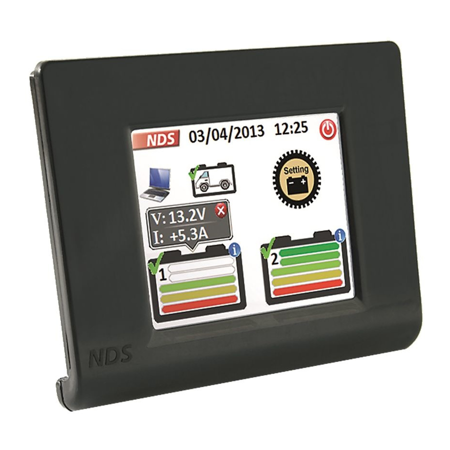
Switching on the device discharging. When the communication cable is connected, the display turns on and the initial screen appears, with the "iManager" writing which will keep displaying until the device 5.4 Displaying Data has not received the first data from the BlackBox. - Page 14 By confirming, all the data inserted earlier are 100% saved and you get to the iManager main screen. The state of charge of the battery in use is represented by coloured bars, whereas the bars of the deactivated battery are grey. The meaning of the bars remains unchanged.
- Page 15 ICON MEANING AND FUNCTIONS 5.1 Main Screen Represents the parallel connection of batteries The iManager main screen shows the information on the batteries’ state of charge (SoC), the date and time. Represents battery charging Main Screen with 1 Battery Main Screen with 2 Batteries Window showing data on battery voltage and charge and discharge current.
-
Page 16: Manual Mode
MEANING AND FUNCTIONS ICON MEANING AND FUNCTIONS NDS ENERGY S.r.l. company logo, if pressed and held displays the Settings Key, if quickly clicked on allows to access commands, if company’s complete data. pressed and held allows to access the initial settings menu.
Need help?
Do you have a question about the iMANAGER and is the answer not in the manual?
Questions and answers