Table of Contents
Advertisement
Available languages
Available languages
Quick Links
In USA - BEST Hartford, Wisconsin
In CANADA - BEST Drummondville, QC, Canada
REGISTER YOUR PRODUCT ONLINE AT : www.BestRangeHoods.com/register
For additional Information visit www.BestRangeHoods.com
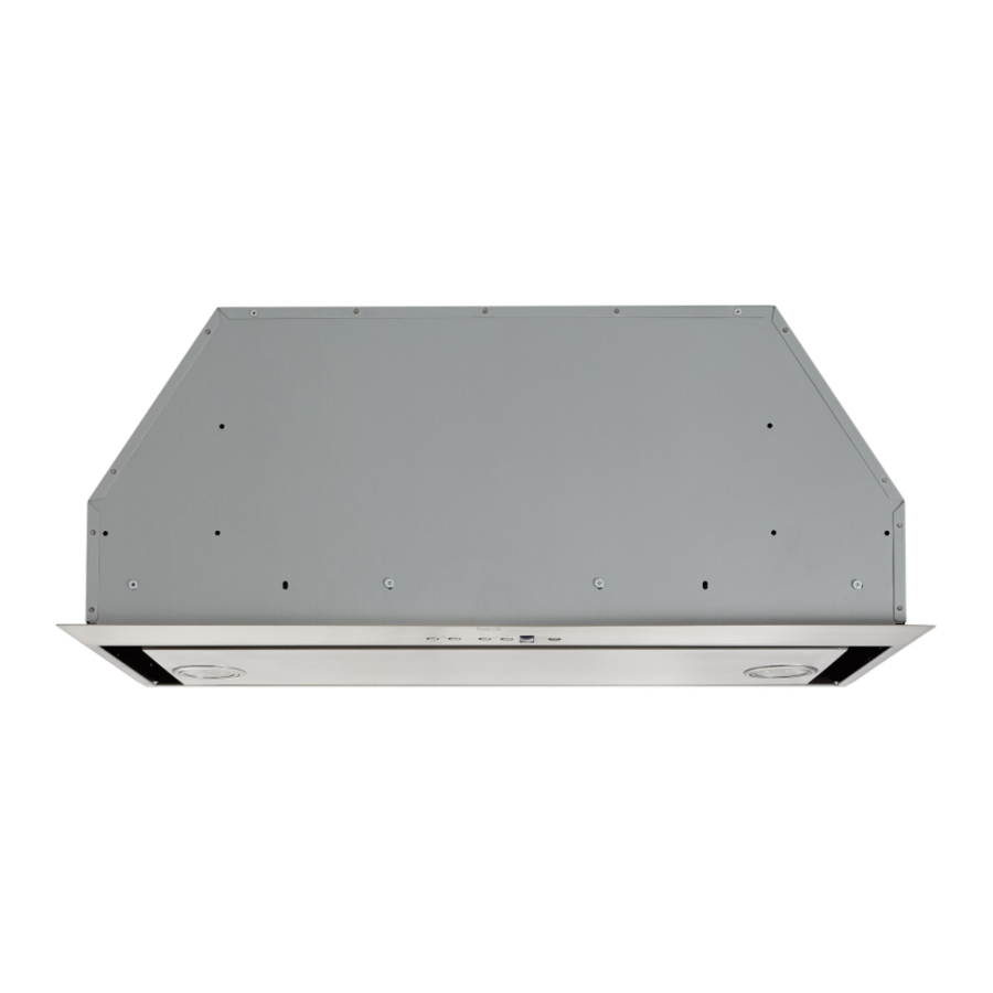
Model P195P
- 1 -
ENGLISH.....................................2
FRANÇAIS..................................12
ESPAÑOL...................................22
Advertisement
Table of Contents

Subscribe to Our Youtube Channel
Related Manuals for BEST Range Hoods P195P


Summary of Contents for BEST Range Hoods P195P
- Page 1 Model P195P ENGLISH........2 FRANÇAIS........12 ESPAÑOL........22 In USA - BEST Hartford, Wisconsin In CANADA - BEST Drummondville, QC, Canada REGISTER YOUR PRODUCT ONLINE AT : www.BestRangeHoods.com/register For additional Information visit www.BestRangeHoods.com - 1 -...
-
Page 2: To Reduce The Risk Of Injury To Persons In The Event Of A Range Top Grease Fire, Observe The Following
READ AND SAVE THESE INSTRUCTIONS INTENDED FOR DOMESTIC COOKING ONLY WARNING TO REDUCE THE RISK OF FIRE, ELECTRIC SHOCK, OR INJURY TO PERSONS, OBSERVE THE FOLLOWING: 1. Use this unit only in the manner intended by the manufacturer. If you have questions, contact the manufacturer at the address or telephone number listed in the warranty. - Page 3 CAUTION 1. For indoor use only. 2. To reduce risk of fi re and to properly exhaust air, be sure to duct air outside. Do not vent exhaust air into spaces within walls or ceilings or into attics, crawl spaces, or garages.
-
Page 4: Prepare The Hood
PREPARE THE HOOD Unpack hood and check contents. 1 - Hood 1 - Hardware Bag (B08084041) containing: Mounting Screws (4,2 x 20 mm Pan Head) 1 - Parts Bag (B08084042) containing: 1 - Junction Box 1 - Junction Box Cover 2 - Cover Screws (3,9 x 6 Flat Head) 4 - Washer 2 - Mounting Screws (3,9 x 9,5mm Pan Head) -
Page 5: Install The Ductwork
INSTALL DUCT CONNECTOR DUCTED CONFIGURATION 1. Install the damper duct connector onto the ROOF CAP hood using mounting screws (3,9x9,5mm) as shown in Fig.2 ROUND DUCT 2. Remove the tape located on the damper. See Fig.2. INSTALL JUNCTION BOXE WALL In the area marked “120 VAC INPUT”, place HOOD a junction box on the top of the hood. -
Page 6: Install The Hood
INSTALL THE HOOD Fig.5 1. Cut a hole in the bottom of the cabinet. See Fig.5 2. To install the hood, adjust the position of the clasping side spring by turning the screws, according to the thickness of the cabinet to which it is going to be anchored. -
Page 7: Maintenance
MAINTENANCE Grease Filters The grease fi lter/s should be cleaned frequent- ly. Use a warm detergent solution. Grease fi lters are dishwasher safe. To take off the grease fi lter/s fi rst open the closure panel pulling downwards. See Fig.10 To take off... -
Page 8: Operation
OPERATION The hood is operated using the (5) push buttons located on the front edge of the hood. The Light Off switch turns the lights off and on. The Light Intensity switch increases and decreases the lighting level. The Blower Off /Speed switch turns the blower off and changes blower speed to four diff... - Page 9 HALOGEN SPOTLIGHT This range hood requires two halogen bulbs (Type T3, 12Volt, 20Watt Max, G-4 Base). WARNING: Always switch off the electricity supply before carrying out any operations on the appliance. 1. Open the cover by prying from the proper slots. See Fig. 12. 2.
- Page 10 Limited Warranty Warranty Period and Exclusions: Broan-NuTone, LLC(the “Company”) warrants to the consumer purchaser of its product (“you”) that the product (the “Product”) will be free from material defects in the materials or its workmanship for a period of fi ve (5) years from the date of original purchase (or such longer period as may be required by applicable law) or a period of two (2) years from the date of service for any labor provided on the Product.
-
Page 11: Service Parts
SERVICE PARTS KEY No. PART No. DESCRIPTION B003100148 FRAME - ONLY FOR P195P1M52 MODEL B003100147 FRAME - ONLY FOR P195PM70 MODEL B02011013 SPRING B08087694 GREASE FILTER - ONLY FOR P195P1M52 MODEL B08087527 GREASE FILTER - ONLY FOR P195PM70 MODEL B02300804 HEAT SENSOR B08093332 BLOWER BRACKET -... - Page 12 LISEZ ET CONSERVEZ CES INSTRUCTIONS POUR USAGE DOMESTIQUE SEULEMENT AVERTISSEMENT AFIN DE RÉDUIRE LES RISQUES D’INCENDIE, D’ÉLECTROCUTION OU DE BLESSURES CORPO- RELLES, SUIVEZ LES INSTRUCTIONS SUIVANTES : 1. N’utilisez cet appareil que de la façon prévue par le fabricant. Pour d’autres renseigne- ments, contactez le fabricant à...
- Page 13 AVERTISSEMENT AFIN D’ÉVITER TOUS RISQUES DE BLESSURE LORS D’UN FEU DE CUISINIÈRE, OBSERVEZ LES INSTRUCTIONS SUIVANTES* : 1. ÉTOUFFEZ LES FLAMMES à l’aide d’un couvercle hermétique, une plaque à biscuits ou un plateau en métal, puis éteignez le brûleur. ATTENTION DE NE PAS VOUS BRÛLER.
-
Page 14: Préparation De La Hotte
PRÉPARATION DE LA HOTTE Retirer la hotte de l’emballage, puis vérifi er le contenu. 1 - Hotte 1 - Sac de visserie (B08084041) comprenant : 4 - Vis de montage (4,2 x 20 mm à tête ronde) 1 - Sac de pièces (B08084042) comprenant: 1 - Boîte de jonction 1 - Couvercle de la boîte de jonction 2 - Cache-vis (3,9 x 6 mm à... - Page 15 INSTALLATION DU RACCORD HOTTE À ÉVACUATION DE CONDUIT CAPUCHON DE TOIT 1. Installer le raccord de conduit à la hotte à l’aide des vis de montage (3,9 mm x 9,5 mm) CONDUIT ROND comme sur Fig.2. 2. Retirer le ruban situé sur le clapet.Voir Fig.2. INSTALLATION DE LA BOÎTE CAPUCHON DE MUR...
-
Page 16: Installation De La Hotte
INSTALLATION DE LA HOTTE Fig.5 DÉCOUPER UN TROU DANS LA BASE DE L’ARMOIRE 1. Découper un trou dans le fonde de l’armoire. Voir Fig.5. 2. Pour installer la hotte, régler la position du ressort de fi xation latéral en tournant les vis, selon l’épaisseur du panneau à... -
Page 17: Entretien
RACCORDEMENT DU CONDUIT 1. Utiliser un conduit rond en métal de 6 ou 8 po pour relier le raccord de conduit sur la hotte au conduit au-dessus. 2. Sceller hermétiquement les joints à l’aide de ruban à conduits. ENTRETIEN Filtres à graisses Les fi... - Page 18 FONCTIONNEMENT La hotte s’utilise à l’aide des (5) boutons-poussoirs situés sur le devant de la hotte. Le commutateur Arrêt lumière active et désactive les lumières. Le commutateur Intensité luminèuse augmente et diminue le niveau d’éclairage. Le commutateur Extinction/vitesse souffl ante permet d’éteindre la souffl ante ou de régler sa vitesse sur quatre positions : haute, moyenne-haute, moyenne-basse et basse.
- Page 19 AMPOULE HALOGÈNE Cette hotte requiert deux ampoules halogènes (Type T3, 12Volt, 20Watt Max, G-4 Base). AVERTISSEMENT: Toujours couper l’alimentation électrique avant d’eff ectuer toute opération sur l’appareil. 1. Ouvrez le couvercle en faisant levier dans les fentes appropriées.Voir Fig. 12. 2.
- Page 20 produit ou la pièce à l’entreprise, conformément à ses instructions, vous devez emballer adéquatement le produit ou la pièce; l’entreprise n’est pas responsable des dommages survenus durant le transport. L’entreprise se réserve le droit d’utiliser des produits ou pièces remis à neuf, réparés ou remanufacturés aux fi ns de réparation ou de remplacement dans le cadre de la garantie.
-
Page 21: Liste Des Pièces De Rechange
LISTE DES PIÈCES DE RECHANGE N° REPÈRE N° DE PIÈCE DESCRIPTION B003100148 GRILLE - SEULEMENT POUR MODELE P195P1M52 B003100147 GRILLE - SEULEMENT POUR MODELE P195PM70 B02011013 RESSORT B08087694 FILTRE À GRAISSES - SEULEMENT POUR MODELE P195P1M52 B08087527 FILTRE À GRAISSES - SEULEMENT POUR MODELE P195PM70 B02300804 DÉTECTEUR DE CHALEUR HEAT SENTRY... - Page 22 LEA Y CONSERVE ESTAS INSTRUCCIONES INDICADO PARA EL USO EN COCINAS DOMESTICAS ADVERTENCIA PARA EVITAR EL RIESGO DE INCENDIO, CORTOCIRCUITO O DAÑO PARA LAS PERSONAS, OBSERVE ATENTAMENTE LAS SIGUIENTES NORMAS: 1. Use esta unidad solamente de la manera indicada por el fabricante; si tiene dudas, póngase en contacto con éste a la dirección o teléfono indicados en la garantía.
- Page 23 ADVERTENCIA 1. Para uso en interiores. 2. Para reducir el riesgo de incendios y para evacuar correctamente los humos, ase- gurarse de haber realizado una conducción del aire hasta el exterior. No expulsar los humos en espacios cerrados por paredes o techos, áticos, espacios angostos o garajes.
-
Page 24: Prepare La Campana
PREPARE LA CAMPANA Sacar la campana de l’embalaje y controlar el contenido. 1 - Campana 1 - Bolsita (B08084041) con: 4 - Tornillos de montaje (4,2 x 20mm cabeza redonda) 1 - Parts Bag (B08084042) con: 1 - Caja de conexiónes 1 - Tapa de la caja 2 - Tornillo de la tapa (3,9 x 6 cabeza plana) 4 - Arandelas... - Page 25 INSTALACION DEL CASQUILLO DE VERSIÓN ASPIRANTE UNION CON EL TUBO CUBIERTA DEL TEJADO 1. Sujete el casquillo de unión en la parte su- perior de la campana; asegura por medio TUBO de tornillos de montaje (3.9x9.5mm) como se muestra en Fig.2 2.
-
Page 26: Instalacion Electrica
INSTALACION DE LA CAMPANA Fig.5 1. Hacer en la base del armario la abertura necesaria. Ver Fig.5 2. Para instalar la campana, regular la posición del enganche laterale por medio 10¼” de los tornillos destinados a este propósito, considerando el espesor del panel hora- dado sobre el que se fi... -
Page 27: Mantenimiento
ENTUBADO DE CANALIZACION 1. Use un tubo de metal de 6” o 8” de diámetro unir el casquillo que se encuentra encima de la campana al tubo de extracción situado arriba. 2. Use cinta para ajustar todas las junturas y que quede hermético. MANTENIMIENTO Filtros anti-grasa Los filtros anti-grasa deben limpiarse a... -
Page 28: Mando A Distancia
FUNCIONAMIENTO La campana se opera mediante los 5 botones pulsadores que se encuentran en el frontal de la campana. El interruptor de apagado de la luz se enciende y apaga las luces. El interruptor de intensidad de la luz aumenta y disminuye el nivel de iluminación. El interruptor de apagado/velocidad del ventilador apaga el ventilador y cambia su velocidad a cuatro ajustes: alta, mediana-alta, mediana-baja y baja. - Page 29 LAMPARAS HALOGENAS Este tipo de campana necesita dos (2) lám- paras halógenas (Tipo T3, 12Volt, 20Watt max, G-4 Base). ATENCIÓN: antes de proceder a cualquier operación, es necesario desconectar el aparato. Para cambiar las lámparas: 1. Abra la tapa haciendo palanca sobre las hendiduras apropiadas.
- Page 30 o la pieza a la Compañía, conforme a las instrucciones de la misma, Usted tendrá que empaquetar el Producto o la pieza correctamente; la Compañíano es responsable de los daños que ocurran durante el transporte. La Compañíase reserva el derecho de utilizar Productos o piezas reacondicionados, renovados, reparados o remanufacturados para la reparación o el reemplazo bajo esta garantía.
-
Page 31: Piezas De Servicio
PIEZAS DE SERVICIO CLAVE N° PIEZA N° DESCRIPCIÓN B003100148 MARCO - SÓLO PARA EL MODELO P195P1M52 B003100147 MARCO - SÓLO PARA LOS MODELOS P195PM70 B02011013 RESSORT B08087694 FILTRO ANTIGRASA - SÓLO PARA EL MODELO P195P1M52 B08087527 FILTRO ANTIGRASA - SÓLO PARA EL MODELO P195PM70 B02300804 SENSOR DE TEMPERATURA B08093332... - Page 32 SERVICE PARTS - PIÈCES DE RECHANGE - PIEZAS DE SERVICIO 99045018F 04308930/1 - 32 -...
Need help?
Do you have a question about the P195P and is the answer not in the manual?
Questions and answers