Advertisement
Quick Links
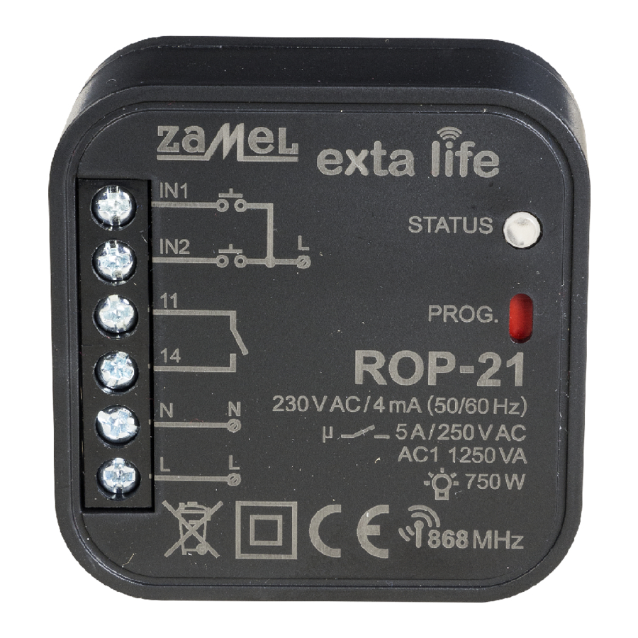
1-CHANNEL RADIO FLUSH RECEIVER
ROP-21
TECHNICAL DATA
Nominal supply voltage:
Nominal frequency:
Nominal power consumption:
Transmission:
Transmission way:
Coding:
Operating range:
Optical signalling (transmission / program-
ming):
Number of paired buttons:
Current receiver's mode information:
Operating modes in cooperation with EXTA
LIFE system transmitters:
Operating modes in cooperation with EXTA
LIFE controller:
Number of external inputs:
Cooperation with push-buttons*:
Operating modes for external inputs**:
Time adjustment range:
Number of output channels:
Relay contact parameters:
Maximum output load:
Number of terminal clamps:
Casing mounting:
Operating temperature range:
Protection degree:
Protection class:
Dimensions:
Weight:
Reference standards:
* switch type configured by means of the EXTA LIFE mobile application
** operating mode dependent on selected switch type
230 VAC
50/60 Hz
0,45 W – standby / 0,8 W – switched on output
radio – ISM band 868 MHz
two-way - 9600 bps
algorithm based on 128-bit key
up to 330 m in the open area
yes – RGB LED
maximum 96 pairs
yes – in the EXTA LIFE mobile application
switch on /switch off, bistable, time
switching on, switching off, time
2
monostable (push-buttons), bistable
only switching on, only switching off, bistable,
monostable, time, switch on/switch off
1 sec. ÷ 18 hrs.
1
1 x NO 5A / 250 VAC (NO dry contact)
incandescent and halogen lighting sources – 750 W
LEDs – 60 W
CFL lamps – 250 W
6 (wires with cross-section up to 2,5 mm²)
Ø60 mm junction box
-10 do +55 °C
IP20
II
47,5 x 47,5 x 20 mm
0,04 kg
EN 60669, EN 60950, EN 61000 ETSI EN 300 220-
1, ETSI EN 300 220-2
Advertisement

Related Manuals for Zamel ROP-21


Summary of Contents for Zamel ROP-21
- Page 1 1-CHANNEL RADIO FLUSH RECEIVER ROP-21 TECHNICAL DATA Nominal supply voltage: 230 VAC Nominal frequency: 50/60 Hz Nominal power consumption: 0,45 W – standby / 0,8 W – switched on output Transmission: radio – ISM band 868 MHz Transmission way: two-way - 9600 bps...
- Page 2 The receiver can additionally be used to control electro valves in heating systems. Current mode of the device controlled by ROP-21 is shown in the mobile application, due to a two- way communication between a receiver and a controller. This method of communication allows for parameterisation of a receiver and a remote adding of transmitters (without a physical access to a receiver).
-
Page 3: Installation
(system without time retrigger). 2. The maximum output load must be obeyed: Time switch on is programmed in the range from 1 sec. to 18 hrs. In case of ROP-21 receiver, it is • incandescent and halogen lamps: 750 W / channel possible to adjust an independent time for each push-button programmed in time mode, for local • fluorescent CFL lamps: 250 W / channel... - Page 4 • Push-buttons can be programmed directly in a receiver by means of the PROG. push-button dure (Step 2). In case of ROP-21 receiver, an individual time can be assigned to each push-button (an access to a receiver is required) or remotely (without an access to a receiver) by means of added to its memory.
- Page 5 5. In the ‘Operation mode’ field select the mode the transmitter should cooperate with a receiver (). In case of ROP-21 the switch on / switch off, bistable, monostable and time modes are possible. The following cases can occur during time mode programming: 6.
- Page 6 REMOTE PROGRAMMING OF TIME ZONE BY MEANS OF EXTA LIFE APLICATION Remote zone time change for ROP-21 receiver is also possible by means of a mobile application. In case we want to delete remotely transmitter’s push-buttons from a receiver, it is required that To do it, pair the particular receiver with the EXTA LIFE system controller.
- Page 7 REGISTRATION (PAIRING) ROP-21 IN THE EXTA LIFE SYSTEM In order to register ROP-21 in the system, it is necessary to connect the EXTA LIFE controller in the system and to install the EXTA LIFE mobile application. The receivers must be connected to 230 V AC.
- Page 8 INPUT FUNCTIONALITY • The structure of outputs is designed to a long term trigger, which is very important during switch • The IN1 and IN2 inputs are used in a wired control of the ROP-21 receiver’s output. They application. are fully configured by means of the EXTA LIFE mobile application. The configuration means...
-
Page 9: Remote Software Update
OUTPUT MODE CONFIGURATION AFTER POWER SUPPLY SWITCH ON In case of ROP-21 receiver, it is possible to configure its input operation mode after power supply has been switched on. As a default setting, the receiver’s input is switched off. Possible output modes: •...
Need help?
Do you have a question about the ROP-21 and is the answer not in the manual?
Questions and answers