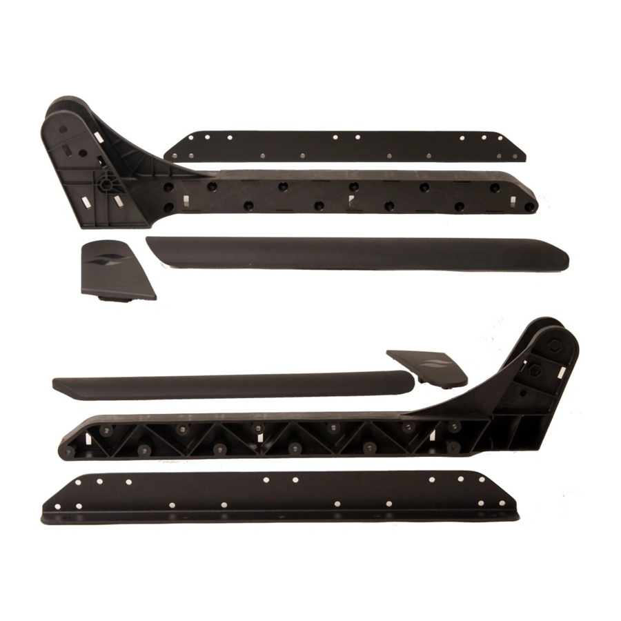
Leisure Concepts Covermate III Instructions
Hide thumbs
Also See for Covermate III:
- Installation manual ,
- Installation instructions (2 pages) ,
- Installation instructions (2 pages)
Advertisement
Table of Contents
Instructions pour le montage du lève-couverture - Updated as of 08/30/12
Step #1
Position the spa cover (in closed position) on the spa making sure that all four corners are properly positioned and square on
the spa.
Placez la couverture dans la position fermée sur le spa en vous assurant que les quatre angles soient correctement
positionnés.
Step #2
Install the ball studs on each mounting bracket (See Fig
. Installez les supports des vérins hydrauliques (boules) sur les 2 supports. (figure 1a)
Step #3
Install the wind lock bar on the determined bracket side, (See Fig. 1b) Note: lightly tighten nut, washer and bolt
combination so that the lock bar moves freely.
Installez la barre de sécurité anti vent sur le côté du support. (figure 1b) Note : la barre doit rester libre, ne serrez pas
trop le boulon.
Step #4
Install the metal plate, rubber stop and pivot arm bolt assembly, (See Fig.1c - 1d). Note: The metal plate MUST be installed
on the inside of the bracket that the Wind Lock Bar is attached to. The 3 1/4" bolts must be installed on the side with
the metal plate.
Installez la plaque métallique, l'arrêt en caoutchouc et assemblez à l'aide du boulon le bras de pivot. (figure 1c/1d)
Note : Tous les assemblages doivent rester libres.
Step #5
Using the #12 x 1-1/2" screws, attach the left and right mounting brackets to the appropriate sides of the spa. Brackets should
be mounted 4" from the back of the spa, directly beneath the lip of the spa (see Fig. 2).
Fixez les supports sur les côtés du spas avec les vis *12 x 1-1/2 " Les supports doivent être montés à 4" (10cms) de
l'arrière du spa, directement en-dessous du retour acrylique de la coque. (figure 2)
Step #6
Starting with the left side first, lay the long end of the cover support arm on the top of the cover, lying parallel to the spa cover
hinge about 1/2" away. Slide the U-shaped retainer clip between the two cover halves with the horizontal part touching the
underside of the cover hinge. (see Fig. 3)
Posez le bras côté gauche d'abord. Insérez l'attache en U entre les deux moitiés de couverture en faisant toucher
la partie horizontale sur le dessous de la charnière. (figure 3)
Step #7
Slide the left and right pivot arms onto the short end of the support arms (See Fig. 3) Note: Do not insert self-tapping
screws at this time, this will be completed in step #9.
Assemblez les bras aux supports. (figure 3) Note : Les bras doivent rester libres à cette étape. (finalisez à l'étape 9)
Step #8
Next, install the ball studs to the left and right pivot arms. Place the two Hex Dome Caps over the Ball Stud Lock Nuts. Note:
Be sure that the ball is pointing away from the spa. (see Fig. 4).
Installez les supports des vérins hydrauliques (boules) sur les 2 bras. (figure 4)
Step #9
With the coupler piece and support arms adjusted properly (about 1/2" away from cover hinge and centered on spa), using
the #10 self tapping screws, fasten support arms to pivot arms and center coupler piece to the support arms (see Fig. 5).
Note: Be sure to rotate the coupler piece so that the inserted screws are at a horizontal angle with the screw head
facing the
Fixez le tube central aux bras avec les vis auto taraudeuses en ajustant l'écartement afin d'avoir la même
dimension entre les supports et les bras. (figure 5)
Step #10
Using the Covermate, lift the cover off the spa and place it in the upright position. Snap the gas shocks on the ball studs.
Note: Be sure to install Gas Shocks with the black body on top. (see Fig. 6 for complete look).
Covermate III
1a)
Advertisement
Table of Contents

Summary of Contents for Leisure Concepts Covermate III
- Page 1 Covermate III Instructions pour le montage du lève-couverture - Updated as of 08/30/12 Step #1 Position the spa cover (in closed position) on the spa making sure that all four corners are properly positioned and square on the spa. Placez la couverture dans la position fermée sur le spa en vous assurant que les quatre angles soient correctement positionnés.
- Page 2 Ouvrez la couverture et placez-la avec le lève-couverture en position verticale. Clipsez le vérin hydraulique sur les supports. (figure 6) Step #11 Attach the 3/8” Rubber Sleeve to the end of the Pivot Arm that the Wind Lock Bar latches onto. (see Fig. 7). Posez les amortisseurs en caoutchouc sur les embouts de bras.


Need help?
Do you have a question about the Covermate III and is the answer not in the manual?
Questions and answers