Table of Contents
Advertisement
Advertisement
Table of Contents

Related Manuals for FlyTech POS485


Summary of Contents for FlyTech POS485
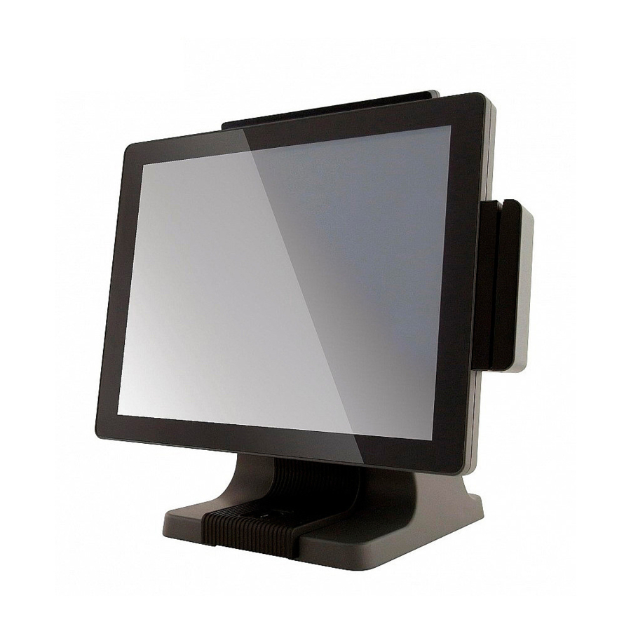
- Page 1 USER MANUAL VERSION 2.0 Setptember 2018 All-in-One Point-of-Sale Hardware System...
- Page 2 Copyright 2018 All Rights Reserved Manual Version 2.0 The information contained in this document is subject to change without notice. We make no warranty of any kind with regard to this material, including, but not limited to, the implied warranties of merchantability and fitness for a particular purpose. We shall not be liable for errors contained herein or for incidental or consequential damages in connection with the furnishing, performance, or use of this material.
- Page 3 CE MARK This device complies with the requirements of the EEC directive 2004/108/EC with regard to “Electromagnetic compatibility” and 2006/95/EC “Low Voltage Directive”. This device complies with part 15 of the FCC rules. Operation is subject to the following two conditions: (1) This device may not cause harmful interference.
- Page 4 LEGISLATION AND WEEE SYMBOL 2012/19/EU Waste Electrical and Electronic Equipment Directive on the treatment, collection, recycling and disposal of electric and electronic devices and their components. The crossed dust bin symbol on the device means that it should not be disposed of with other household wastes at the end of its working life.
- Page 5 Revision History Changes to the original user manual are listed below: Revision Description Date • Initial release Novenber 2010 • C68 MB added NOvember 2011 • B68 MB removed December 2013 • C76 MB added • D36 and D66 MB added April 2014 •...
-
Page 6: Table Of Contents
Table of Contents 1. Packing List ........1 1-1. Standard Accessories .............1 1-2. Optional Accessories ............2 2. System View ........3 2-1. Front & Side View ............3 2-2. Rear View with stand ............3 2-3. I/O Ports View ..............4 2-4. System Dimension ............5 3. - Page 7 ........ 20 ....... 22 6-1. D36 V2.1 Motherboard ..........22 6-1-1. Motherboard Layout ............22 6-1-2. Connectors & Functions ..........23 6-1-3. Jumper Setting ..............24 6-2. D36 V4.0 Motherboard ..........26 6-2-1. Motherboard Layout ............26 6-2-2. Connectors & Functions ..........27 6-2-3. Jumper Setting ..............28 6-3.
- Page 8 The page is intentionally left blank. viii...
-
Page 9: Packing List
Packing List 1-1. Standard Accessories a. System b. Driver CD c. Power adapter d. Power cord e. RJ45-DB9 cable (x2) -
Page 10: Optional Accessories
1-2. Optional Accessories a. MSR module b. VFD module (with RJ-45 cable) c. Second display (with VGA cable) d. Fingerprint module or iButton module e. Wall mount kit Cable cover... -
Page 11: System View
System View 2-1. Front & Side View Description Touch screen MSR module (optional) Rugged footprint Ventilation HDD door 2-2. Rear View with stand Description VFD dummy cover MSR dummy cover... -
Page 12: I/O Ports View
2-3. I/O Ports View D36 Motherboard c d e Description HDD slot Printer Power button DC-IN COM port 1, 2, 3 (from right to left) USB 2.0 (x4) Cash drawer Power switch USB 3.0 (x1) D66 Motherboard f g h Description Printer COM port 1, 2, 3 (from right to left) -
Page 13: System Dimension
D86S Motherboard c d e f g hi Description Printer COM port 1, 2, 3 (from right to left) USB 2.0 (x2) Cash drawer COM5 Power switch Display port Line out Power button DC-IN USB type C USB 3.0 (x3) 2-4. -
Page 14: System Assembly & Disassembly
System Assembly & Disassembly 3-1. Stand Disassembly 1. Loosen the thumb screw (x1) and slide the stand towards the IO panel to release it from the system. 2. Reverse the steps above to attach stand to the system. 3-2. Power Adapter Replacement Power adapter is secured to the system stand by a holding bracket and screws. -
Page 15: Hd Replacement
3-3. HD Replacement To remove the HDD from the System: 1. Power the system down. 2. Remove the screw(x1) from the HDD door. 3. Open the HDD door. 4. While pinching the HDD bracket tabs pull the HDD from the system. For easier removal pull the plastic puller (see picture) at the same time. -
Page 16: Open The System
2. To install a new HDD, attach the HDD to the bracket until it clicks in place. Make sure to press the edges of the drive not the center to avoid damaging the drive. 3. Finally slide the HDD into the slot till it clicks. -
Page 17: Ram Replacement
3-5. RAM Replacement 1. Follow the steps in Chapter 3-4 to open the system. 2. The RAM is located on the right side of the system (see picture). Installing a RAM module 3. Slide the memory module into the memory slot and press down until it locks in place. -
Page 18: Peripherals Installation
Peripherals Installation 4-1. MSR Installation MSR module can be installed to either side of the system. Choose one side and follow the steps below. Make sure the unit is powered down before starting. 1. Remove the screws (x2) to release the MSR dummy cover. -
Page 19: Fingerprint Installation
4-2. Fingerprint Installation Fingerprint module will be installed to system prior to shipping once it is selected. 1. Loose the thumb screw (x1) securing the module and slide the module outward as arrow shown. 2. Loose the screw (x1) fastening the ground cable and disconnect the cable from the connector. -
Page 20: Vfd Installation
4-3. VFD Installation 1. Follow steps in Chapter 3-1 to disassemble the system stand. 2. Attach the VFD module to system by fastening the screws (x2). 3. Route the cable through cable mangement on the system stand. 4. Connect the RJ-45 cable to COM port on the systems IO panel. Make sure the system is powered off. -
Page 21: Second Display Installation
4-4. Second Display Installation 1. Follow steps in Chapter 3-1 to disassemble the system stand. 2. Connect one end of the VGA cable to 2nd Display. Route the cable through cable mangement on the system stand. 3. Attach the 2nd Display to system by fastening the screws (x2). 4. -
Page 22: Wall Mounting Kit Installation
4-5. Wall Mounting Kit Installation The Wall mounting Kit includes a wall plate, a metal bracket, and one screw. (refer to Chapter 1-2 item e). Please follow the steps below. 1. Secure the wall plate to the wall by fastening screws (x4). 2. -
Page 23: Cable Cover Installation
4. Fasten the screw (x1) through the metal bracket to secure the wall mount kit. 4-6. Cable Cover Installation There are two different cable covers. These can be utilized separately or together. When both are needed, please take care that they are installed in the correct order. 1. -
Page 24: Cash Drawer Installation
4-7. Cash Drawer Installation 4-7-1. For D36 / D86S Motherboard You can install a cash drawer through the cash drawer port. Please verify the pin assignment before installation. Cash Drawer Pin Assignment Signal Cash drawer 2 In Cash drawer 1 Out Cash drawer 1 In 12V / 19V (or 24V) Cash drawer 2 Out... - Page 25 Bit 7: Reserved Bit 6: Reserved Bit 5: Reserved Bit 4: Cash Drawer 1 pin output control. = 1: Opening the Cash Drawer = 0: Allow close the Cash Drawer Bit 3: Cash Drawer 1 pin input control. = 1: the Cash Drawer closed or no Cash Drawer = 0: the Cash Drawer opened Bit 2: Reserved Bit 1: Reserved...
-
Page 26: For D66 Motherboard
4-7-2. For D66 Motherboard You can install a cash drawer through the cash drawer port. Please verify the pin assignment before installation. Cash Drawer Pin Assignment Signal DOUT bit0 DIN bit0 12V / 19V DOUT bit1 Cash Drawer Controller Register The Cash Drawer Controller use one I/O addresses to control the Cash Drawer. - Page 27 Bit 7: Reserved Bit 6: Cash Drawer “DIN bit0” pin input status. = 1: the Cash Drawer closed or no Cash Drawer = 0: the Cash Drawer opened Bit 5: Reserved Bit 4: Reserved Bit 3: Cash Drawer “DOUT bit1” pin output control. = 1: Opening the Cash Drawer = 0: Allow close the Cash Drawer Bit 2: Cash Drawer “DOUT bit0”...
- Page 28 Model name POS485 Motherboard D86S Intel HaswellCPU LGA-1150 22nm Intel SkylakeS i5-4570S 2.9GHz, LLC 6MB, TDP 65W, i7-6700 3.4G L3 8MB, 65W Intel Bay Trail CPU Celeron J1900 AMT 9.0 i5-6500 3.6G, L3 6M,65W CPU support 2.0GHz, L2 2M i3-4330 3.5GHz, LLC 3MB, TDP 54W I3-6100 3.7G, L3 4M, 51W...
- Page 29 Model name POS485 Motherboard D86S Environment EMC & Safety FCC, Class A, CE, LVD Operating temperature 0°C ~ 35°C (32°F ~ 95°F) Storage temperature -20°C ~ 60°C (-4°F ~ 140°F) Storage humidity 20% ~ 85% RH non condensing Dimension (W x D x H)
-
Page 30: D36 V2.1 Motherboard
6-1. D36 V2.1 Motherboard 6-1-1. Motherboard Layout CN13 CN12 SATA1 CN14 USB2 CN24 RJ45_1 USB1 CN23 CN15 CN10 JP1 CN17 CN11 MINI_PCIE1 USB3 CN18 CN25 BAT1 CN19 DDR3_A1 CN20... -
Page 31: Connectors & Functions
6-1-2. Connectors & Functions Connector Function Front I/O board Inverter connector LVDS connector System FAN connector LPT port connector Speaker & MIC connector 40pin external connector CN10 HDD LED connector CN11 Power LED connector CN12 SATA power connector CN13/14 USB port (internal) CN15 PS2 keyboard connector CN17... -
Page 32: Jumper Setting
6-1-3. Jumper Setting Inverter Selection Function CCFL Cash Drawer Power Setting Function COM1/COM2/COM3 Power Setting COM1, COM2 and COM3 can be set to provide power to your serial device. 1. Power on the system, and press the <DEL> key when the system is booting up to enter the BIOS Setup utility. - Page 33 LCD ID Setting LVDS Output Panel# Resolution Bits Channel Interface LVDS 800 x 600 Single Panel LVDS 800 x 600 Single Panel LVDS 1024 x 768 Single Panel LVDS 1024 x 768 Single Panel LVDS 1366 x 768 Single Panel LVDS 1366 x 768 Single...
-
Page 34: D36 V4.0 Motherboard
6-2. D36 V4.0 Motherboard 6-2-1. Motherboard Layout CN34 CN32 CN13 CN12 CN33 SATA1 CN31 USB2 RJ45_1 USB1 CN7 CN1 USB3 MINI_PCIE1 BAT1 CN19 DDR3_A1 CN27 CN29... -
Page 35: Connectors & Functions
6-2-2. Connectors & Functions Connector Function C N 1 / C N 1 3 / C N 2 1 / Internal USB connector CN29 EC Debug CPU FAN connector LPT connector 40Pin connector CN12 SATA power connector CN18 COM5 (touch) connector CN19 Wide range power connector CN25... -
Page 36: Jumper Setting
6-2-3. Jumper Setting Cash Drawer Power Setting Function COM1/COM2/COM3 Power Setting COM1, COM2 and COM3 can be set to provide power to your serial device. 1. Power on the system, and press the <DEL> key when the system is booting up to enter the BIOS Setup utility. -
Page 37: D66 Motherboard
6-3. D66 Motherboard 6-3-1. Motherboard Layout USB5 MINI_PCIE1 CN10 RJ45_1 CN24 USB3 CN13 CN12 CN14 USB1 CN16 CPU1 CN19 DDR3_A CN20... -
Page 38: Connectors & Functions
6-3-2. Connectors & Functions Connector Function SATA power connector Inverter connector LVDS connector CPU FAN connector System FAN connector HDD LED connector Speaker & MIC connector CN9/10 USB port (internal) CN11 Power LED connector CN12 40pin external connector CN13 EC Debug CN14 Printer connector CN15... -
Page 39: Jumper Setting
6-3-3. Jumper Setting Inverter Selection Function CCFL Cash Drawer Power Setting Function COM1/COM2/COM3 Power Setting COM1, COM2 and COM3 can be set to provide power to your serial device. 1. Power on the system, and press the <DEL> key when the system is booting up to enter the BIOS Setup utility. - Page 40 LCD ID Setting LVDS Output Panel# Resolution Interface Bits Channel LVDS 800 x 600 Single Panel LVDS 800 x 600 Single Panel LVDS 1024 x 768 Single Panel LVDS 1024 x 768 Single Panel LVDS 1366 x 768 Single Panel LVDS 1366 x 768 Single...
-
Page 41: D86S Motherboard
6-4. D86S Motherboard 6-4-1. Motherboard Layout DIMM_A1 CN10 CPU1 CN11 CN13 BAT1 CN16 CN15 CN12 CN22 CN21 SKT1 CN18 CN14 CN19 SKT2 CN17 CN6 CN5 SATA1... -
Page 42: Connectors & Functions
6-4-2. Connectors & Functions Connector Function System FAN connector eDP connector HDD power connector USB connector CN4 /8 / 12 MIC-In connector Audio connector(right) Audio black connector M.2 connector Power LED connector CN10 Audio connector(left) CN11 40 pin external connector CN13 CN14 Printer connector... -
Page 43: Jumper Setting
6-4-3. Jumper Setting Cash Drawer Power Setting Function COMBO Speaker Setting Function Enagle Jumper open COM1/COM2/COM3 Power Setting COM1, COM2 and COM3 can be set to provide power to your serial device. 1. Power on the system, and press the <DEL> key when the system is booting up to enter the BIOS Setup utility. -
Page 44: Appendix: Drivers Installation
Appendix: Drivers Installation and utility that enables you to install the drivers on the system. Please insert the Driver CD into the drive and double click on the “index.htm” to select the models. You can refer to the drivers installation guide for each driver in the “Driver/ Manual List”.
Need help?
Do you have a question about the POS485 and is the answer not in the manual?
Questions and answers