Table of Contents
Advertisement
Advertisement
Table of Contents

Related Manuals for FlyTech POS 554


Summary of Contents for FlyTech POS 554
- Page 1 USER MANUAL VERSION V1.0 AUG 2010 MiniPOS Hardware System...
- Page 2 Copyright 2010 August All Rights Reserved Manual Version 1.0 Part Number: 3LMPPA530110 The information contained in this document is subject to change without notice. We make no warranty of any kind with regard to this material, including, but not limited to, the implied warranties of merchantability and fitness for a particular purpose.
-
Page 3: Important Safety Instructions
Safety IMPORTANT SAFETY INSTRUCTIONS To disconnect the machine from the electrical power supply, turn off the power switch and remove the power cord plug from the wall socket. The wall socket must be easily accessible and in close proximity to the machine. Read these instructions carefully. -
Page 4: Legislation And Weee Symbol
CAUTION ON LITHIUM BATTERIES There is a danger of explosion if the battery is replaced incorrectly. Replace only with the same or equivalent type recommended by the manufacturer. Discard used batteries according to the manufacturer’s instructions. LEGISLATION AND WEEE SYMBOL 2002/96/EC Waste Electrical and Electronic Equipment Directive on the treatment, collection, recycling and disposal of electric and electronic devices and their components. -
Page 5: Revision History
Revision History Changes to the original user manual are listed below: Revision Description Date • Initial release 2010 August... -
Page 6: Table Of Contents
Table of Contents 1. Packing List ......1 1-1. Standard Items ............1 1-2. Optional Items ............1 2. System View ......2 2-1. Front View ...............2 2-2. Top View ..............2 2-3. Side View ..............3 2-4. Rear View ..............3 2-5. I/O view ..............4 2-6. - Page 7 6. Jumper Setting ......13 6-1. Motherboard Layout ..........13 6-2. Connectors & Functions .........14 6-3. Jumper Setting ............15 Appendix: Drivers Installation ..18...
-
Page 8: Packing List
Packing List 111. Standard Items a. System d. Power adapter b. Driver bank e. Power cord c. User guide f. RJ45-DB9 cable (x2) Note: Power cord will be supplied differently according to various region or country. 112. Optional Items g. WLAN card... -
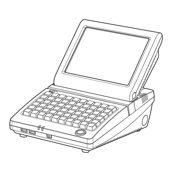
Page 9: System View
System View 211. Front View Touch Screen Power Button 212. Top View Keyboard iButton Power LED HDD Indicator... -
Page 10: Side View
213. Side View Ventilation Speaker Cable Blind Hole 214. Rear View Cable Cover... -
Page 11: I/O View
212. I/O view a b c d Item No. Description DC-IN 19V DC-OUT 24V Cash Drawer COM1, 2, 3, 4 PS/2 Screws for fixing the keyboard 2nd VGA Parallel... -
Page 12: Dimensions & View Angles
216. Dimensions & View Angles 224mm 75° 60° 45°... -
Page 13: System Assembly
System Assembly 311. Display Tilt Angle Adjustment Take apart the rubber hinge covers (x2) at both sides. Loose screws (x2) inside for adjust- ment. 3. Take apart the rubber hinge covers (x2) near the ventilation holes. 4. Remove screws (x2) inside to adjust display tilt angle. -
Page 14: Open The Cable Cover
312. Open the Cable Cover Turn to the rear side of the sytem. Open the cable cover by lifting upward (as arrow shown). To put it back, do parallely push the cable cover untill you hear clicking sound. -
Page 15: Ram Module Replacement
313. RAM Module Replacement Before Replacement Follow the steps at 3-2 to open the cable cover at the back. Remove screws (x2) on upper side of the I/O panel. Slide and open the keyboard. Removing a RAM module Find the memory slow at the left inside of the motherboard. -
Page 16: Hdd Replacement
314. HDD Replacement To remove and replace the HDD, please follow the steps below. Follow the steps at 3-2 to open the cable cover at the back. Loose the screw (x1) on HDD holding bracket. Pull the screw to slide bracket out of the system. -
Page 17: Power Adapter Installation
312. Power Adapter Installation The system is equipped with a 90W power adapter. Please plug it into the system as shown below. Follow the steps at 3-2 to open the cable cover at the back. Find the power connector on the left side of the I/O panel.(refer to 212 a. -
Page 18: Peripheral Installation
Peripheral Installation 411. WLAN Installation Follow the steps of “Before Re- placement” at 3-3 to open the system. Find the PCI-E WLAN card at the right side of the mother- board. Aux:Grey There are 2 wires installed with- in the system: black and grey. Connect the black wire to Main connector while connect the grey to Aux. -
Page 19: Specification
Specification Motherboard C32 V0.9B Processor Intel® Atom N270 processor 1.6GHz L2 512K FSB 533MHz Chipset Intel® 945GSE Express + ICH7M System Memory 1 x DDR2 DIMM up to 2GB Graphic Memory Share System Memory up to 232MB Storage Device Hard Drive 1 x 2.5"... -
Page 20: Jumper Setting
Jumper Setting 611. Motherboard Layout CN29 CN28 CN15 CN21 FAN-SYS3 SATA2 CN24 CN25 CN6 CN5 BAT1 DDR2_A1 SKT3 SATA1 CN14 CN10 CN16 JP10 CN13 CN27 MINI_PCIE3 JP10 CN31 CN30 JP11 CN9 JP8 CN22 CN12 PWR3 PWR4 RJ45_4 USB3 RJ11_3 RJ45_3 Version: C35 v0.9B... -
Page 21: Connectors & Functions
612. Connectors & Functions Connector Purpose Audio Line Out CN4 / CN25 Power Connector for HDD CN5 / CN6 USB Connector LAN LED Connector MSR Connector CN10 / CN14 T-CON Connector CN12 IrDA Connector CN13 Inverter Connector CN15 Power LED Connector CN21 Internal Power Switch Connector CN24... -
Page 22: Jumper Setting
613. Jumper Setting 61311. System Reset Function JP7 (1-2) ▲Normal Reset 61312. COM3 & COM4 Power Setting Function 5 7 9 11 ▲RI 6 8 10 12 5 7 9 COM3 Pin10 8 10 5 7 9 +12V 8 10 5 7 9 ▲RI 8 10... - Page 23 61313. Cash Drawer Power Setting Function +12V ▲+19V 61314. Power Mode Setting Function ▲ATX Power AT Power 61312. CMOS Operation Mode Function JP6 (1-2) ▲Normal Reset ▲ = Manufacturer Default Setting...
- Page 24 61316. LCD ID Setting LVDS Output Panel# Resolution Bits Channel Interface 1366 x 768 Single LVDS 1440 x 990 Dual LVDS 1920 x 1080 Dual LVDS 1024 x 768 Single LVDS 1280 x 1024 Dual LVDS 800 x 600 Single LVDS 1024 x 768 Single...
-
Page 25: Appendix: Drivers Installation
Appendix: Drivers Installation The shipping package includes a Driver CD in which you can find every individual driver and utility that enables you to install the drivers on the system. Please insert the Driver CD into the drive and double click on the “index.htm” to select the models.
Need help?
Do you have a question about the POS 554 and is the answer not in the manual?
Questions and answers