Yanmar 4JH3-TE Operation Manual
Marine diesel engine
Hide thumbs
Also See for 4JH3-TE:
- Service manual (103 pages) ,
- Service manual (100 pages) ,
- Operation manual (57 pages)

Subscribe to Our Youtube Channel
Related Manuals for Yanmar 4JH3-TE


Summary of Contents for Yanmar 4JH3-TE
- Page 1 OPERATION MANUAL Be sure to read this manual for safe and proper operation. Store this manual carefully after use.
- Page 2 • If giving your engine to someone else, be sure to attach this Operation Manual. • Constant efforts are made to improve the quality and performance of Yanmar prod- ucts, so some details included in this Operation Manual may differ slightly from your engine.
-
Page 3: Table Of Contents
2.2.1 4JH3-TE ........ - Page 4 6.3 Consulting Your Yanmar Dealer or Distributor ........
-
Page 5: For Safe Operation
1. FOR SAFE OPERATION 1. FOR SAFE OPERATION Following the precautions described in this manual will enable you to use this engine with complete satisfaction. Failure to observe any of the rules and precautions, however, may result in injury, burns, fires, and engine damage. Read this manual carefully and be sure you fully understand it before beginning operation. -
Page 6: Safety Precautions
1. FOR SAFE OPERATION 1.2 Safety Precautions (Observe these instructions for your own safety.) Precautions for Operation Burns from Scalding • Never remove the filler cap of the fresh water cooler while the engine is still hot. Steam and hot water will spurt out and seriously burn you. Wait until the water temperature has dropped, then wrap a cloth around the cap and loosen it slowly. - Page 7 1. FOR SAFE OPERATION Alcohol • Never operate the engine while you are under the influence of alcohol or when you are ill or feel unwell as this results in accidents. Safety Precautions for Inspection Battery Fluid • Battery fluid is diluted sulfuric acid. It can blind you if it gets in your eyes, or burn your skin.
-
Page 8: Location Of Product Safety Labels
1. FOR SAFE OPERATION 1.3 Location of Product Safety Labels To insure safe operation, product safety labels have been attached. Their location is shown in the diagram below. Keep the labels from becoming dirty or torn and replace them if they are lost or damaged. Also replace labels when parts are replaced, ordering them in the same way as for the parts. -
Page 9: Product Explanation
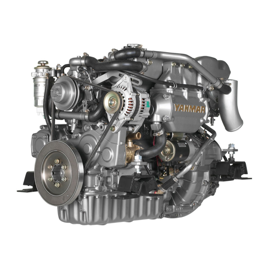
This is light, compact diesel elngine for use in pleasure boats. The engine is equipped with a turbocharger and intercooler which insures maximum output while preserving lightness and compact size. (The 4JH3-TE /- TCE are equipped with the turbocharger only.) Power output for this group of engines increases progressively from 4JH3-TE(4JH3-TCE), 4JH3-THE to 4JH3-DTE. -
Page 10: Engine Specifications
2. PRODUCT EXPLANATION 2.2 Engine Specifications 2.2.1 4JH3-TE Engine model 4JH3-TE Pleasure boat Type Vertical water-cooled 4-cycle diesel engine × φ × No. of cyl.-bore stroke Displacement 1.995 Aspiration Turbooharged Cont. rating kW{hp}/rpm 50.7(69) / 3700 kW{hp}/rpm *55.2(75)/3800 Max. output (Crankshaft) **53.5(72.8)/3800... -
Page 11: 4Jh3-Tce
2. PRODUCT EXPLANATION 2.2.2 4JH3-TCE Engine model 4JH3-TCE Pleasure boat (Sailing boat) Type Vertical water-cooled 4-cycle diesel engine × φ × No. of cyl.-bore stroke Displacement 1.995 Aspiration Turbooharged Cont. rating kW{hp}/rpm 50.7(69)/3700 kW{hp}/rpm *55.2(75)/3800 Max. output (Crankshaft) **53.5(72.8)/3800 ± High idling 4300 ±... -
Page 12: 4Jh3-Hte
2. PRODUCT EXPLANATION 2.2.3 4JH3-HTE Engine model 4JH3-HTE Pleasure boat Type Vertical water-cooled 4-cycle diesel engine × φ × No. of cyl.-bore stroke Displacement 1.995 Aspiration Turbooharged Cont. rating kW{hp}/rpm 67.7(92)/3700 kW{hp}/rpm *73.6(100)/3800 Max. output (Crankshaft) **71.4(97)/3800 ± High idling 4300 ±... -
Page 13: 4Jh3-Dte
2. PRODUCT EXPLANATION 2.2.4 4JH3-DTE Engine model 4JH3-DTE Pleasure boat Type Vertical water-cooled 4-cycle diesel engine × φ × No. of cyl.-bore stroke Displacement 1.995 Aspiration Turbooharged Cont. rating kW{hp}/rpm 85.3(116)/3700 kW{hp}/rpm *91.9(125)/3800 Max. output (Crankshaft) **89.1(121.3)/3800 ± High idling 4300 ±... -
Page 14: Names Of Parts
V-belt Clutch lever Seawater pump Starter motor Oil cooler(Marine gear) NOTE: The 4JH3-DTE engine with KMH4A is used as the example for the above drawings. The 4JH3-TE is not equipped with an intercooler (indicated by * mark in the above). -
Page 15: Major Servicing Parts
2. PRODUCT EXPLANATION 2.4 Major Servicing Parts Name of part Function Fuel filter Removes dust and water from fuel. The filter is a cartridge type, and the inner element should be replaced before clogging occurs. A water separator is on the bottom of the filter and should be drained periodically. Fuel priming pump This is a manual fuel pump. -
Page 16: Operation Equipment
2. PRODUCT EXPLANATION 2.5 Operation Equipment Explanation of the equipment used to operate the engine. 2.5.1 Instrument Panel OPTION The instrument panel is located in the cockpit, separate from the engine. The following instruments enable you to start and stop the engine and to monitor its condition during operation. ♦... - Page 17 2. PRODUCT EXPLANATION (1) Meters The following meters are located in the upper center part of the instrument panel. ♦B/C and New B/C type panels use analog electric systems and have a pointer indicator. Turn the panel light switch (illumination switch) ON for easy viewing. •...
- Page 18 2. PRODUCT EXPLANATION (3) Starter Switch This is the switch for starting engine operation. It is a rotary-type 3-step switch. Position is changed by turn- ing the key in the switch. is the position where the engine is stopped. All current is cut off. The key can be inserted and removed in this position.
-
Page 19: Remote Control Handle
2. PRODUCT EXPLANATION 2.5.2 Remote Control Handle This engine is controlled by the remote control handle located in the cockpit. The speed control lever on the engine side and clutch lever on the marine drive are connected by remote control cable with the various remote control handles in the cockpit (We reccomend you a single hanrdle remote control device). - Page 20 2. PRODUCT EXPLANATION Operation of the handle is as follows: • Starting and stopping Put the handle in NEUTRAL. This puts the clutch in the cut-off position (stop) and idles the engine at a low speed. • Forward Move the handle from NEUTRAL to ∆FWD(forward). This engages the clutch in forward and simultaneously increases the engine speed.
- Page 21 2. PRODUCT EXPLANATION (2) Trawling Handle OPTION KMH4A The trawling control is a single remote control handle. The marine gear trawling lever operates by remote con- trol cable. The operation labels on the handle are: Tighten Normal operation H:Highest trawling speed and normal (not trawling) Trawling operation position.
-
Page 22: Before Operation
3. BEFORE OPERATION 3. BEFORE OPERATION Perform items 3.1 – 3.7 before starting to prepare for operation. 3.1 Fuel Oil, Lube Oil and Cooling Water 3.1.1 Fuel Oil (1) Selection of Fuel Oil Use the following diesel fuels or equivalents. Select fuels of a higher quality for best engine performance. -
Page 23: Lube Oil
3. BEFORE OPERATION 3.1.2 Lube oil (1) Selection of Engine Lube Oil Use the following lube oil: *API Classification CD (Standards of America Petroleum Institute) *SAE Viscosity 15W40 (Standards of Society of Automotive Engineering) NOTICE: Using other than the specified lube oil will lead to seizure of parts inside the engine and gear device , abnormal wear, and shorten engine life. -
Page 24: Supplying Fuel
3. BEFORE OPERATION 3.2 Supplying Fuel Fires from Oil Ignition • Be sure to use the correct type of fuel when refueling. Mistakenly filling with gasoline or the like will result in ignition. • Be sure to stop the engine before refueling. If you spill fuel, wipe such spillage carefully. -
Page 25: Supplying Engine Lube Oil
3. BEFORE OPERATION 3.3 Supplying Engine Lube Oil Fill with the specified amount of engine oil. Oil Inlet 1. Remove the oil inlet cap on the top of the bonnet and fill with oil. 2. Remove the oil dipstick and check the level of the oil with the gauge on the stick. -
Page 26: Supplying Cooling Water
Fill the fresh water tank and the subtank with fresh cooling water. 1. Before filling, check to be sure the drain cocks (indicated in the diagram) are closed. 4JH3-TE /TCE Turbocharger Exhaust manifold... -
Page 27: Cranking
3. BEFORE OPERATION 3.6 Cranking When the engine is being used for the first time or if it has not been used for a long period of time, perform cranking before starting to distribute oil to all of the parts. Using an engine which has been stored for a long period of time without the cranking procedure may result in engine seizure, since there will no longer be oil on the moving parts after storage. -
Page 28: How To Operate
4. HOW TO OPERATE 4. HOW TO OPERATE Alcohol • Never operate the engine while you are under the influence of alcohol or when you are ill or feel unwell as this results in accidents. Exhaust Gas Poisoning • Be sure to establish good ventilation in the engine room with windows, vents, or other ventilation equipment. - Page 29 If the cooling water runs out too often, or if the water level in the fresh water tank falls with- out any change in the subtank water level, there may be some leakage of water or air. In such cases, consult your Yanmar dealer or distributor without delay. (6) Checking the Remote Control Handle Be sure to check that the remote control handle lever moves smoothly before use.
-
Page 31: Starting
4. HOW TO OPERATE 4.3 starting 4.3.1 Daily Starting Follow the following procedures for starting under nor- NEUTRAL mal conditions. NEUTRAL 1. Open the Kingston cock. (option) 2. Open the fuel tank cock. (option) 3. Cut off all clutches and main switches for all auxiliary machinery so that there is no load. -
Page 32: After The Engine Has Started
4. HOW TO OPERATE 4.3.4 After the Engine has Started (1) Warming-up running After the engine has started, let it run for about 5 minutes. This warms up the engine and distributes oil to all of the parts. NOTICE: The engine will seize if it is operated when cooling seawater discharge is too small or if load is applied without any warming up operation. -
Page 33: Clutch Operation For The Marine Gear
4. HOW TO OPERATE 4.5 Clutch Operation for the Marine Gear 4.5.1 Forward, Neutral, Reverse Use the remote control handle to operate the clutch for the marine gear (FORWARD, NEUTRAL, REVERSE). • Be sure to run the engine at the lowest possible speed when changing between FORWARD and REVERSE. -
Page 34: Check During Operation
4. HOW TO OPERATE 4.6 Check During Operation Always be on the lookout for problems during engine operation. Pay particular attention to the following. (1) Is sufficient water being discharged from the seawater outlet pipe? If the discharge is small, stop the engine immediately, identify the cause and repair. (2) Is the exhaust color normal? The continuous emission of black exhaust shows engine overloading. -
Page 35: Stopping The Engine
4. HOW TO OPERATE 4.7 Stopping the Engine Stop the engine in accordance with the following proce- Stop button dures. 1. Stop the boat. Put the remote control handle in NEUTRAL and STOP reduce the engine speed to the lowest speed. 2. -
Page 36: Operation Procedure
4. HOW TO OPERATE 4.8 Operation Procedure The following diagram shows the procedures for operation explained up to this point. Parts of the operation may differ depending on the remote control system being used. Accompanying operation manuals should be read carefully and understood. Inspection Before Starting Starting Operation Starting the Engine... -
Page 37: Long-Term Storage
1. Open the water drain cock on the marine gear oil cooler and drain off the cooling water. (The position of the drain cock varies with the different types of marine gears.) 4JH3-TE/-TCE 2. Open the water drain cock on the seawater cooling pipe and drain off the cooling water. -
Page 38: Checking The Engine For Reuse After A Long Storage Period
1. Open the fresh water drain cocks at the following 4 positions and drain off the cooling water. 1) Side of the cylinder block 2) fresh water pump 3) turbocharger 4JH3-TE/-TCE 4) exhaust manifold 4JH3-HTE 4JH3-DTE or fresh water cooler 2. -
Page 41: Periodic Inspection Items
5. MAINTENANCE & INSPECTION 5.2 Periodic Inspection Items 5.2.1 Inspection After Initial 50Hrs. Operation (1) Replacing the Engine Lube Oil and Lube Oil Filters (1st time) Precautions for Removing Hot Oil to Prevent Bums If extracting oil from the engine while it is still hot, do not let the oil splash on you. - Page 42 5. MAINTENANCE & INSPECTION (2) Replacing the Marine gear Oil and Washing the Oil Filters (1st time) Precautions for Removing Hot Oil to Prevent Bums If extracting oil from the engine while it is still hot, do not let the oil splash on you.
-
Page 43: Inspection Every 50 Hours
5. MAINTENANCE & INSPECTION 5.2.2 Inspection Every 50 Hours (1) Draining the Fuel Tank OPTION 1. Put a pan under the drain to catch the fuel. 2. Loosen the drain cock at the bottom of the fuel tank, and drain off any water and dirt collected inside. 3. - Page 44 The capacity of the specified alternator and battery is sufficient for regular operation, how- ever, the capacity may be insufficient if they are used for other purposes such as lights inside the boat, etc. Consult your Yanmar dealer or distributor.
-
Page 45: Inspection Every 250 Hrs. Or 1 Yr
5. MAINTENANCE & INSPECTION 5.2.3 Inspection Every 250 Hrs. or 1 yr. (1) Replacing the Fuel Filter Replace the fuel filter periodically before there is clog- ging and the fuel flow is reduced. 1. Close the fuel cock of the fuel tank. Tighten 2. - Page 46 5. MAINTENANCE & INSPECTION (4) Replacing the Marine Gear Oil and Washing the Oil Filter (2nd time) Replace the marine gear oil for the 2nd time. Wash the filter at the same time. →See 5.2.1(2) KMH4A (5) Adjusting the Remote Control Handle The remote control handles and the engine speed control lever and clutch shifting lever are connected by an remote-control cable.
- Page 47 5. MAINTENANCE & INSPECTION (5C) Adjusting the Position of the Trawling Remote Control Handle OPTION KMH4A 1. Check to see that the trawling lever on the marine Normal Trawling operation gear side is in the high speed position when the trawl- Trawling ing remote control handle is in H(high speed) position.
-
Page 48: Inspection Every 500 Hrs.or 2 Yrs
5.2.4 Inspection Every 500 Hrs.or 2 yrs. (1) Adjustment of Intake/Exhaust Valve clearance This maintenance requires specialized knowledge. Consult your Yanmar dealer or distributor. Adjustment is necessary to maintain the correct timing for the opening and closing of valves. Neglecting adjustment will cause the engine to run noisily and result in reduced power output and other damage. -
Page 49: Inspection Every 1000 Hrs. Or 4 Yrs
If water leaks continuously from the seawater pump during operation disassembly and maintenance (replace- ment of the mechanical seal) are necessary. When disassembly and maintenance of the seawater pump are necessary, consult your Yanmar dealer or distributor. (3) Washing the Cooling Water System and Checking and Maintaining Parts This maintenance requires specialized knowledge. - Page 50 5. MAINTENANCE & INSPECTION (4) Checking and Replacing the fuel pipe and the cooling water pipe This maintenance requires specialized knowledge. Consult your Yanmar dealer or distributor. Check the hoses of the fuel and cooling water pipings and replace if damaged.
-
Page 52: Trouble And Troubleshooting
6. TROUBLE AND TROUBLESHOOTING Trouble Probable Cause Measure Reference Starting Failures Starter works. No fuel Replenish fuel; bleed. but engine does not start. Air in fuel line Bleed. 3.2.2 Bad fuel Replace with recommended fuel. 3.1.1 Clogged fuel filter Replace fuel filter. 5.2.3(1) Poor fuel injection Ask for repairs. -
Page 53: Emergency Repairs For Marine Gear Trouble
The emergency bolt should only be used in cases where it is impossible to operate the clutch and the boat must return to port. Ask your Yanmar dealer for repairs immediately after returning to port. • When using the emergency bolt, never use the clutch as this will break it. -
Page 54: Consulting Your Yanmar Dealer Or Distributor
If the problem has already been reviewed with the Service Manager, contact the owner of the dealership or the General Manager. • If you problem still has not been resolved to your satisfaction, contact your Yanmar local Subsidiary Com- pany. (See the back cover of this manual) We will need the following information in order to assist you: •... - Page 55 MEMO...
-
Page 56: System Diagram
7. SYSTEM DIAGRAM 7. SYSTEM DIAGRAM 7.1 Wiring diagram 7.1.1 B type Instrument Panel (Optional) 1/2 (Panel side) Color coding Starter switch Detail of Engine stop switch coupler AA Illumi. (lamp check) switch Starter SW Charge C.W. Temp. Eng. Oil Press. - Page 57 7. SYSTEM DIAGRAM 2/2 (Engine side) (Customer) Battery (Cross sectional area of wire) Battery SW Eng. stop mag. valve Neutral SW Air heater Starter motor Starter relay C.W. temp. SW Eng. oil press. SW Earth bolt Alternator C.W. temp. sender Not available for B type Tacho sensor (Eng.
-
Page 58: C Type / C Type × B Type(No.2 Station) Instrument Panel
7. SYSTEM DIAGRAM 7.1.2 C type / C type × B type(No.2 station) Instrument Panel (Optional) 1/2 (Panel side) Starter switch Relay Engine stop switch Illumi. (lamp check) switch Starter SW C.W. Temp. Eng. Oil Press. Buzzer Tachometer B type (No.2 station) Hour M Tacho M Eng. - Page 59 7. SYSTEM DIAGRAM 2/2 (Engine side) (Customer) Battery (Cross sectional area of wire) Eng. stop Battery SW mag. valvee Neutral Air heater Starter relay Starter motor Eng. Oil Press SW C.W. temp. SW Earth bolt Alternator Tacho sensor C.W. temp. sendor Optional Color coding Eng.
-
Page 60: New B Type Instrument Panel
7. SYSTEM DIAGRAM 7.1.3 New B type Instrument Panel (Optional) 1/2 (Panel side) Starter switch Color coding Detail of coupler Detail of coupler Buzzer stop Illumi. Buzzer Tachometer with hour meter Eng. stop switch Starter switch Charge Eng.Oil Press. C.W. Temp. Sail Drive Leak Extension harness... - Page 61 7. SYSTEM DIAGRAM 2/2 (Engine side) (Customer) Battery (Cross sectional area of wire) Battery SW Eng. stop mag. valvee Neutral Air heater Starter relay Starter motor C.W. Temp. SW Eng. Oil Press SW Earth bolt Alternator Tacho sensor Fuel filter Optional Local supplied sail drive leak sensor.
-
Page 62: New C Type / New C Type × New B Type(No.2 Station)
7. SYSTEM DIAGRAM 7.1.4 New C type / New C type × New B type(No.2 station) Instrument Panel (Optional) 1/2 (Panel side) Relay Buzzer stop Illumi. Buzzer Tachometer with hour meter Eng. stop SW Starter SW Eng. Oil Press. C.W. Temp. Sail Drive Leak Fuel Emp. - Page 63 7. SYSTEM DIAGRAM 2/2 (Engine side) (Customer) Battery (Cross sectional area of wire) Battery SW Eng. stop mag. valvee Neutral Air heater Starter relay Starter motor C.W. Temp. SW Eng. Oil Press SW Earth bolt Alternator Tacho sensor C.W. temp. sendor Optional Eng.
- Page 64 Models : Marine Engine Code No. Operation Manual 49961-202851 4JH3-TE/-TCE/-HTE/-DTE...
Need help?
Do you have a question about the 4JH3-TE and is the answer not in the manual?
Questions and answers