Yanmar 4JH3-TE Series Operation Manual
Hide thumbs
Also See for 4JH3-TE Series:
- Service manual (103 pages) ,
- Service manual (100 pages) ,
- Operation manual (65 pages)
Table of Contents
Advertisement
JH-Turbo-Engels1a
30-06-2002
13:17
Pagina 1
MARINE DIESEL ENGINE
MODELS:
4JH3-TE/-HTE/-DTE/-TCE Series
OPERATION MANUAL
GB
California
Proposition 65 Warning
Diesel engine exhaust and some of
its constituents are recognized by
the State of California to cause
cancer, birth defects, and other
reproductive harm.
Advertisement
Table of Contents

Subscribe to Our Youtube Channel
Related Manuals for Yanmar 4JH3-TE Series


Summary of Contents for Yanmar 4JH3-TE Series
-
Page 1: Proposition 65 Warning
JH-Turbo-Engels1a 30-06-2002 13:17 Pagina 1 MARINE DIESEL ENGINE MODELS: 4JH3-TE/-HTE/-DTE/-TCE Series OPERATION MANUAL California Proposition 65 Warning Diesel engine exhaust and some of its constituents are recognized by the State of California to cause cancer, birth defects, and other reproductive harm. - Page 2 State's stringent anti-smog standards. All States Yanmar warrants that the engine is: (1) designed, built and equipped so as to conform with all applicable emissions regulations, including in California, all applicable regulations adopted by the Air Resources Board; and (2) free from defects in materials and workmanship which cause such engine to fail to conform with applicable emissions regulations for its warranty period.
- Page 3 Yanmar is liable for damages to other engine components caused by the failure of any war- ranted part during the warranty period.
-
Page 4: Table Of Contents
JH-Turbo-Engels1a 30-06-2002 13:17 Pagina 2 Contents CONTENTS 3.3 Operating your Engine ...... 25 INTRODUCTION ..........3 3.3.1 Inspection Before Starting ..25 3.3.2 How to Start the Engine ..27 1 FOR YOUR SAFETY ........4 3.3.3 Operation........ 28 1.1 Warning symbols ........ 4 3.3.4 Cautions during Operation.. -
Page 5: Introduction
Make sure this manual is transfered to subsequent owners. It should be considered as a permanent part of the engine and remain so. Constant efforts are made to improve the quality and performance of Yanmar products, so some details included in this Operation Manual may differ slightly from your engine. If you have any questions about this, please contact your Yanmar dealer or distributor. -
Page 6: For Your Safety
JH-Turbo-Engels1a 30-06-2002 13:17 Pagina 4 1. For your safety 1.1 WARNING SYMBOLS Most operation, maintenance and inspection problems arise due to users’ failure to comply with the rules and precautions for safe operation described in this operation manual. Often, users do not understand or recognize the signs of approaching problems. Improper handling can cause burns and other injuries and can result in death. - Page 7 JH-Turbo-Engels1a 30-06-2002 13:17 Pagina 5 1. For your safety Battery DANGER Never smoke or permit sparks near the battery, because it may emit explosive hydrogen gas. Place the battery in a well-ventilated place. Fuel DANGER Use only diesel oil. Never use other fuels, including gasoline, kerosene, etc., because they could cause a fire.
- Page 8 JH-Turbo-Engels1a 30-06-2002 13:17 Pagina 6 1. For your safety Alcohol WARNING Never operate the engine while you are under the influence of alcohol. Never operate the engine when you are ill or feeling unwell. SAFETY PRECAUTIONS FOR INSPECTION Battery Fluid DANGER Battery fluid is dilute sulfuric acid.
-
Page 9: Warning Labels
JH-Turbo-Engels1a 30-06-2002 13:17 Pagina 7 1. For your safety SAFETY PRECAUTIONS FOR INSPECTION 1.3 WARNING LABELS Product Safety Labels, Parts Code Numbers 128377-07350 To insure safe operation, warning device 128296-07260 labels have been attached. Their location is shown below and they should always be 128296-07300 visible. -
Page 10: Product Explanation
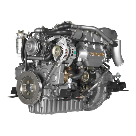
This is a light, compact diesel engine for use in pleasure boats. The engine is equipped with a turbocharger and intercooler which insures maximum output while preserving lightness and compact size. (The 4JH3-TE series is equipped with the turbocharger only.) Power output for this group of engines increases progressively from 4JH3-TE, 4JH3-HTE to 4JH3-DTE. - Page 11 JH-Turbo-Engels1a 30-06-2002 13:17 Pagina 9 2. Product explanation This Operation Manual explains the basic points for standard operation. Variations are explained under the letter emblems for easy reference. Model : Explanation of indicated model only. Option : Explanation of optional parts. Customer : Explanation of use of parts from other boat manufacturers.
-
Page 12: Engine Specifications
JH-Turbo-Engels1a 30-06-2002 13:17 Pagina 10 2. Product explanation Engine Specifications 2.2.1 Item Unit Model Engine Model 4JH3-TE 4JH3-TBE 4JH3-THE 4JH3-TCE vertical 4-cycle water cooled diesel engine Type direct injection Combustion system Number of cylinders Bore x stroke 84 x 90 Displacement 1.995 Aspiration system... - Page 13 JH-Turbo-Engels1a 30-06-2002 13:17 Pagina 11 2. Product explanation 2.2.2 Item Unit Model Engine Model 4JH3-HTE 4JH3-HTBE 4JH3-HTHE vertical 4-cycle water cooled diesel engine Type direct injection Combustion system Number of cylinders Bore x stroke 84 x 90 Displacement 1.995 Aspiration system turbocharger, intercooler Continuous Output/crankshaft...
- Page 14 JH-Turbo-Engels1a 30-06-2002 13:17 Pagina 12 2. Product explanation 2.2.3 Item Unit Model Engine Model 4JH3-DTHE vertical 4-cycle water cooled diesel engine Type Combustion system direct injection Number of cylinders Bore x stroke 84 x 90 Displacement 1.995 Aspiration system turbocharger, intercooler Continuous Output/crankshaft kW/rpm...
-
Page 15: Names Of Parts
* Intercooler V-belt Clutch lever Seawater pump Starter Oil cooler(clutch) NOTE: The 4JH3-DTHE engine (with KMH4A clutch) is used as the example for the above diagram. The 4JH3-TE Series is not equipped with an intercooler (indicated by * in the diagram). -
Page 16: Major Servicing Parts
JH-Turbo-Engels1a 30-06-2002 13:17 Pagina 14 2. Product explanation Major Servicing Parts Name of part Function Fuel filter Removes dust and water from fuel. The internal element (filter) should be changed periodically. A water separator is on the bottom of the filter and should be drained periodically. -
Page 17: Control Equipment
JH-Turbo-Engels1a 30-06-2002 13:18 Pagina 15 2. Product explanation Control Equipment 2.5.1 Control Panel The instrument panel is located in the control room. The following instruments enable you to start/stop the engine and to monitor its condition during operation. B type New B type C type New C type... - Page 18 JH-Turbo-Engels1a 30-06-2002 13:18 Pagina 16 2. Product explanation (1) Metres insufficient oil will result in damage and The following metres are located in the seizure. Check the oil level. upper centre part of the instrument panel. • B/C/D and New B/C/D type panels use 4 FUEL FILTER analog electric systems and have a When the drain inside the water...
- Page 19 JH-Turbo-Engels1a 30-06-2002 13:18 Pagina 17 2. Product explanation (2) Controls and Equipment Controls and Equipment Mechanism Key Switch Rotary switch with 4 positions. In the OFF position, the switch key can be inserted or removed. In OFF, all electric current is cut off. GLOW In ON (1 position to the right), the engine is turned on.
-
Page 20: Remote Control Handle
(clutch remains in the NEUTRAL, no load position). NOTICE Yanmar recommends the use of a single-lever type for the remote con- trol lever. If only the two-lever type is available in the market, operate the... -
Page 21: Gb 2.5.3 Stopping Equipment
JH-Turbo-Engels1a 30-06-2002 13:18 Pagina 19 2. Product explanation 2.5.3 Stopping Equipment KMH4A Clutch Electric Operation Push the stop button on the instrument panel. Continue to push the stop button until the engine has come to a complete stop. Stop button on the instrument panel Trawling lever Low speed (trawling) High speed... -
Page 22: Operation
JH-Turbo-Engels1b 28-06-2002 19:54 Pagina 20 3. Operation 3.1 Fuel Oil, Lube Oil, and Cooling Water (3) Fuel System Install the fuel pipe from the fuel tank to 3.1.1 Fuel Oil the fuel pump in accordance with the diagram. NOTICE When other than the specified fuel Fuel system oil is used, the engine will not perform to full capacity and parts... -
Page 23: Cooling Water
JH-Turbo-Engels1b 28-06-2002 19:54 Pagina 21 3. Operation (3) Handling the Lube Oil Handling of Cooling Water 1) When handling and storing lube oil, be 1. Choose antirust which will not have any careful not to allow dust and water to adverse effects on the materials (cast enter the lube oil. -
Page 24: Before Initial Operation
JH-Turbo-Engels1b 28-06-2002 19:54 Pagina 22 3. Operation 3. Move the priming pump knob up and 3.2 Before Initial Operation down until fuel mixed with air bubbles flows out of the air bleeding bolt and Perform the following before using the tighten the air bleeding bolt. -
Page 25: Supply Clutch Lube Oil
Specifications before shipping from the plant. 3. Tighten the filler port cap securely by hand. KMH4A Clutch 4JH3-TE series NOTICE Do not overfill. Overfilling will cause oil to be sprayed out during operation and affect the efficiency of the marine gear. -
Page 26: Cranking (Idling)
JH-Turbo-Engels1b 28-06-2002 19:55 Pagina 24 3. Operation 3. Pour cooling water slowly into the fresh 3.2.6 Cranking water tank so that air bubbles do not develop. Supply until the water over- When the engine is being used for the first flows from the filler port. -
Page 27: Check And Resupply Lube Oil And Cooling Water
JH-Turbo-Engels1b 28-06-2002 19:55 Pagina 25 3. Operation 3.2.7 Check and Resupply Lube Oil and (1) Visual Checks Cooling Water Check for the following: 1. Lube oil leakage from the engine When engine oil, clutch oil, or cooling 2. Fuel oil leakage from the fuel system water is supplied for the first time or when 3. - Page 28 In such cases, consult your Yanmar dealer or distributor without delay. Note: The water rises in the subtank during engine operation.
-
Page 29: How To Start The Engine
JH-Turbo-Engels1b 28-06-2002 19:55 Pagina 27 3. Operation (2) Starting Under Low Temperature 3.3.2 How to Start the Engine Conditions When starting the engine under difficult (1) Start the engine according to the low temperature conditions (approximately following procedures: 0°C or lower), use the air heater to enable easier starting. -
Page 30: Operation
JH-Turbo-Engels1b 28-06-2002 19:55 Pagina 28 3. Operation (4) After the Engine has Started 3.3.3 Operation After the engine has started, check the following items at a low engine speed: (1) Engine Acceleration and Deceleration 1. Check that the gauges and alarm Use the governor handle to control devices on the instrument panel are acceleration and deceleration. -
Page 31: Cautions During Operation
JH-Turbo-Engels1b 28-06-2002 19:55 Pagina 29 3. Operation (3) Switching to Trawling 3.3.4 Cautions During Operation Use the trawling handle to begin trawling. Always be on the lookout for problems 1. Operation continues at a low engine during engine operation. speed of 1000rpm or less. Pay particular attention to the following: 2. -
Page 32: Stopping The Engine
JH-Turbo-Engels1b 28-06-2002 19:55 Pagina 30 3. Operation speed position and repeat this process 4. Push the stop button on the instrument about 5 times. This is done to clean out panel. carbon from the cylinders and the fuel injection valve. Stop button on the instrument panel Neglecting to race the engine will result in poor exhaust colour and reduce... -
Page 33: Procedure
JH-Turbo-Engels1b 28-06-2002 19:55 Pagina 31 3. Operation 3.3.6 Procedure The following diagram shows the procedures for operation explained up to this point. Parts of the operation may differ depending on the remote control system being used. Accompanying operation manuals should be read carefully and understood. Starting Operation Inspection Before Starting... -
Page 34: Long Term Storage
0°C. cooler, cylinder block, cylinder head, etc.) when ambient tempe- rature is below 0°C. 4JH3-TE Series 1. Open the water drain cocks as illustrated and drain the cooling water. 2. Close the drain cocks after draining the water. - Page 35 JH-Turbo-Engels1b 28-06-2002 19:55 Pagina 33 3. Operation Carry out the next periodic inspection before placing the engine in Waterproof the engine room to storage. Clean the outside of the engine prevent rain and seawater from entering. wiping off any dust or oil. During long term storage, charge To prevent condensation inside the battery once a month to compensate...
-
Page 36: Maintenance & Inspection
Specialized technicians are ready to assist Safety. you with periodic inspections and mainte- The functions of engine components will nance. Consult your YANMAR dealer or degenerate and engine performance will distributor in accordance with the service drop according to the use of the engine. If agreement. -
Page 37: List Of Periodic Inspection Items
JH-Turbo-Engels1b 28-06-2002 19:55 Pagina 35 4. Maintenance & Inspection 4.2 List of Periodic Inspection Items Daily and periodic inspections are important to keep the engine in its best condition. The following is a summary of inspection and servicing items by inspection interval. - Page 38 JH-Turbo-Engels1b 28-06-2002 19:55 Pagina 36 4. Maintenance & Inspection ❍ : Check G : Consult local dealer : Replace System Item Before After 50 Every Every Every starting hrs or one 250 hrs 500 hrs 1000 hrs month (1 year) (2 years) (4 years) ❍...
-
Page 39: Periodic Inspection Items
Add oil if the level is engine use will cause changes in the too low. intake/exhaust valve and rocker arm clear- ance, and adjustment is necessary. This adjustment requires specialized knowledge and techniques. Consult your Yanmar dealer or distributor. -
Page 40: Inspection Every 50 Hours (Or Monthly)
JH-Turbo-Engels1b 28-06-2002 19:56 Pagina 38 4. Maintenance & Inspection 4.3.2 Inspection Every 50 Hours (or Monthly) (1) Draining the Fuel Filter 1. Close the fuel oil cock. 2. Loosen the plug screw at the bottom of the fuel filter oil/water separator, and drain off any water and dirt collected inside. -
Page 41: Inspection Every 250 Hrs
WARNING may be insufficient. In such cases, Before inspecting the electrical system, consult your Yanmar dealer or be sure either to turn off the battery distributor. switch or to disconnect the (-) terminal of the earth cable. Otherwise, a short- circuit could cause a fire. - Page 42 JH-Turbo-Engels1b 28-06-2002 19:56 Pagina 40 4. Maintenance & Inspection Adjust the high speed bolt position first 1. Close the fuel cock. and then adjust the low speed idling. 2. Remove the filter case by loosening the retainer ring (turn to the left) with the filter wrench.
- Page 43 Yanmar dealer or distributor. 4. After about 3 minutes, pour in approximately 50cc of fresh water in the same manner over a period of about...
-
Page 44: Inspection Every 500 Hrs
Inlet This maintenance requires specialized knowledge. 5. After operating the engine for about Consult your Yanmar dealer or distributor. 10 minutes, check the boost pressure and power output. (2) Washing the Cooling Water System If there is no improvement after washing... -
Page 45: Trouble And Troubleshooting
JH-Turbo-Engels1b 28-06-2002 19:56 Pagina 43 5. Trouble and Troubleshooting 5.1 Trouble and Troubleshooting Trouble Probable Cause Measure Reference Alarm Buzzer and Alarm NOTICE Lamps On During Operation Shift to low speed operation immediately, and check which lamp has come on. Stop the engine for inspection. -
Page 46: Emergency Repairs For Clutch
See 5.2, Emergency Repairs for to operate the clutch and the boat Clutch Trouble. must return to port. Ask your Yanmar dealer for repairs immediately after 5.2 Emergency Repairs for Clutch. returning to port. - Page 47 3 for the second bolt, and tighten the Consulting Your Yanmar Dealer or Distributor Refer difficult problems and repairs to your Yanmar dealer or distributor. At the time of trouble, check and report the following: 1. Engine model and number: 2.
- Page 48 Manager, contact the owner of the with the dealer. dealership or the General Manager. • If your problem still has not been resolved to your satisfaction, contact your local Yanmar Subsidiary Com- pany. (See the back of this manual for addresses)
-
Page 49: Piping Diagrams
JH-Turbo-Engels1b 28-06-2002 19:56 Pagina 47 6. Piping diagram (See appendix A at the back of this book) 01 Overflow NOTES: NOTATION 02 Fuel oil inlet Dimension of steel pipe: 03 Piston cooling oil jet outer dia.x thickness 04 Fuel injection pump Dimension of rubber pipe: Rubber hose 05 Lub. -
Page 50: Wiring Diagrams
JH-Turbo-Engels1b 28-06-2002 19:56 Pagina 48 7. Wiring diagrams (See appendix B at the back of this book) 24 Option For B/C-type panel 01 Starter switch 25 Instrument panel Colour coding for wiring 02 Stop switch 26 Buzzer diagrams 03 Switch (lamp chk/illum.) 27 Tachometre 04 Relay 28 Not applicable... - Page 51 THIS MACHINERY PART MUST NOT BE PUT INTO SERVICE UNTIL THE MACHINERY INTO WHICH IT IS TO BE INCORPORATED HAS BEEN DECLARED IN CONFORMITY WITH THE PROVISIONS OF THE DIRECTIVE. • IMPORTER IN THE EU: YANMAR MARINE INTERNATIONAL B.V. Brugplein 11 1332 BS Almere-de Vaart, The Netherlands Nagahama, Japan, Sept. 21, 1997 Place and date issued Y.
- Page 52 JH-Turbo-Engels1b 28-06-2002 19:57 Pagina 49 APPENDIX A Piping diagram 4JH3-TE-HTE-DTE...
- Page 53 JH-Turbo-Engels1b 28-06-2002 19:57 Pagina 50 APPENDIX B Wire diagrams Panel B-2...
- Page 54 JH-Turbo-Engels1b 28-06-2002 19:57 Pagina 51 APENDIX B Wire diagrams Panel C...
- Page 55 GM-VOORWERK 14-06-2002 14:59 Pagina 3 Notes...
- Page 56 GM-VOORWERK 14-06-2002 14:59 Pagina 4 Notes...
- Page 57 GM-VOORWERK 14-06-2002 14:59 Pagina 5 Notes...
Need help?
Do you have a question about the 4JH3-TE Series and is the answer not in the manual?
Questions and answers