Table of Contents
Advertisement
Quick Links
Advertisement
Table of Contents

Related Manuals for Stark TL 7500


Summary of Contents for Stark TL 7500
- Page 1 Original Operating and maintenance manual Road Grader...
-
Page 2: General
For us, the long lifecycle and efficiency of your new equipment is a priority. To keep the road grader in top working condition, read this manual carefully before using the equipment. STARK products are engineered and manufactured in Finland, and each of them is equipped according to the needs of the customer. -
Page 3: Table Of Contents
Table of contents General ..............................2 Read before use ........................... 2 1. DECLARATION OF CONFORMITY ...................... 4 2. PURPOSE OF USE ..........................5 3. SAFETY PRECAUTIONS ........................5 4. IDENTIFICATION INFORMATION AND SPAREPARTS ................ 6 4.1. Identification plate ..........................6 4.2. -
Page 4: Declaration Of Conformity
1. DECLARATION OF CONFORMITY The original manufacturer’s EC declaration of conformity: Generic product name: Road grader Models: TL 7500 Manufacturer: Lametal Ltd Kaskenviertäjäntie 2 73100 LAPINLAHTI, Finland tel. +358 17 731 565 Declares that the above-mentioned equipment meets the provisions of Directive 2006/42/EC on machinery and, where applicable, comply with the standards •... -
Page 5: Purpose Of Use
2. PURPOSE OF USE STARK Road graders are used for grading gravel roads and flat areas and for transferring ice (removal of packed snow). The device can also be used to shape and align fields. 3. SAFETY PRECAUTIONS Make sure you know your equipment before you start using it. Equipment may be operated only by an individual who is thoroughly familiar with its use. -
Page 6: Identification Information And Spareparts
(marked in the identification plate) when you order spare parts. For more information on maintenance and spare parts, please contact the STARK maintenance and spare part services or your retailer. -
Page 7: Main Parts Of The Road Grader
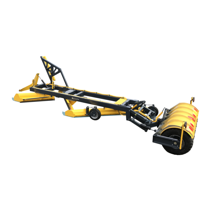
5. MAIN PARTS OF THE ROAD GRADER Picture 2. Main parts of the road grader 1) Frame of the road grader 2) Floating frame 3) Pull shaft 4) Front wing 5) Middle wing 6) Windrow spreader 7) Support wheels for windrow spreader 8) Tire packer 9) Ditch wing (accessory) 10) Extension for windrow spreader (accessory) -
Page 8: Attaching The Road Grader
6. ATTACHING THE ROAD GRADER When attaching the road grader for the first time, make sure it is compatible with the base machine by following the instructions below. Always check the compatibility when attaching the road grader to a new base machine. Make sure that the base machine allows installation of the road grader. -
Page 9: Operating The Road Grader
7. OPERATING THE ROAD GRADER Before operating the road grader, make sure: the road grader is installed correctly all locking pins are in place hydraulic hoses are connected right and properly hoses are intact there are no oil leaks all functions are working properly learn to operate the road grader in a closed area before actually using the device 7.1. -
Page 10: Detaching The Road Grader
7.3. Detaching the road grader When you disconnect the blade assembly from the tractor, lower the assembly on a flat surface and rest it on the blades. Rest the blades on top of strong support brackets. Turn the restrictor valve’s adjustment cap into closed position (picture 3). Lift the ditch wing up with hydraulics, wing locks upward position hydraulically. -
Page 11: Wireless Controller
7.4. Wireless controller Wireless controller is available as an accessory for the road grader, which allows to control all movements of the grader with one 2-action section valve. Controller, it’s fastener and power socket are added to the base machine. Controller is used to control electric valves added to the grader. -
Page 12: Removal Of Packed Snow
7.5. Removal of packed snow It is possible to rotate the middle wing of the road grader to the “packed snow removal” -position. The point of rotating the middle wing is to move ice and snow to the side of the road. Middle wing is rotated by removing the bolts holding it (32 pc of M16 bolts). -
Page 13: Maintaining The Road Grader
8. MAINTAINING THE ROAD GRADER 8.1. General safety precautions for the use and maintenance Comply with the applicable laws and regulations and the instructions in this manual Never go under the road grader if it is not supported Always put on the base machine’s parking brake before any servicing on the road grader. Use only tools which are in good condition. -
Page 14: Daily Maintenance
8.4. Daily maintenance It is important to perform a daily visual inspection of the road grader for early detection of possible faults and to prevent further damage. Inspect the following items on the road grader daily: Hydraulic hoses and components for possible leaks General mechanical condition 8.5. -
Page 15: Lubrication Points
8.7. Lubrication points Picture 7. Lubrication points 1. Peg of the windrow spreader’s shaft 2. Tilting peg of the windrow spreader 3. Peg of the windrow spreader’s support wheel 4. Axle of the windrow spreader’s support wheel 5. Joint bearings of the tire packers’ hydraulic cylinder 6. -
Page 16: Hydraulics
9. HYDRAULICS The road grader is attached to the base machine with 2-, 4- and 8-hose hydraulics. The system has been tested and adjusted by the manufacturer. Any alterations or modifications to the hydraulic system are on the sole responsibility of the client. -
Page 17: 4-Hose Hydraulics
9.2. 4-hose hydraulics With a wireless controller A. Base machine’s control block 1 B. Base machine’s control block 2 C. Pull shaft’s lift cylinder D. Floating frame’s lift cylinder E. Tire packer’s hydraulic cylinder F. Tire packer’s tilting cylinder Figure 2. Hydraulic chart for the 4-hose hydraulics Sivu 17 / 19... -
Page 18: 2-Hose Hydraulics
9.3. 2-hose hydraulics With a wireless controller A. Base machine’s control block 1 B. Pull shaft’s lift cylinder C. Floating frame’s lift cylinder D. Tire packer’s hydraulic cylinder E. Tire packer’s tilting cylinder Figure 3. Hydraulic chart for the 2-hose hydraulics Sivu 18 / 19... -
Page 19: Warranty Policy
3. Warranty period STARK warranty covers a period of one (1) year. If need be, the client and the manufacturer make separate agreements on warranty concerning repairs and spare parts used in repairs. 4. Repairs during the warranty period Repairs during the warranty period are carried out free of charge within the normal working hours by the manufacturer repair and maintenance services or by a repair service provider accredited by the manufacturer.
Need help?
Do you have a question about the TL 7500 and is the answer not in the manual?
Questions and answers