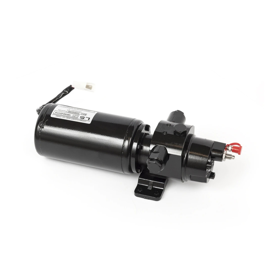
Lecomble & Schmitt RV07 Installing And Bleeding

Lecomble & Schmitt RV07 Installing And Bleeding

Ls power packs for autopilots

Advertisement

Outillage nécessaire pour l'installation
- 1 jeu de clés plates : 7 à 32
- 1 clé à molette
- 1 jeu de tournevis plats
- 1 jeu de clés mâles 6 pans
- 1 cutter
- 1 perceuse + 1 jeu de forets
- 1 paire de tenaille
- 1 clé dynamométrique
S.A.S LECOMBLE & SCHMITT
B.P. n°2 - 64240 URT - FRANCE
;
+33(0)559 562 646 -
@ : commercial2@ls-france.com - : : www.ls-france.com
Tools required for the installation
- 1 set of spanners: 7 to 32
- 1 adjustable spanner
- 1 set of straight screwdrivers
- 1 set of hexagon keys
- 1 cutter
- 1 drilling machine + 1 set of drill bits
- 1 pair of pliers
- 1 torque wrench
1
+33(0)559 569 571
Validé par / Approved by
Date : 23-11-2016

Advertisement

Table of Contents
loading

Summary of Contents for Lecomble & Schmitt RV07

  • Page 1 Outillage nécessaire pour l’installation Tools required for the installation - 1 jeu de clés plates : 7 à 32 - 1 set of spanners: 7 to 32 - 1 clé à molette - 1 adjustable spanner - 1 jeu de tournevis plats - 1 set of straight screwdrivers - 1 jeu de clés mâles 6 pans - 1 set of hexagon keys...
  • Page 2: Table Of Contents

    Hydraulic Connection Drawings for Groupes RV07 – RV1 – RV2 – RV3 ........7 RV07 – RV1 – RV2 – RV3 Power Packs ........7 Groupes EV2 – EV3 – HVR 1/3 .......... 8 EV2 – EV3 – HVR 1/3 Power Packs ..........8 Centrales HF ...............
  • Page 3: Recommandations Importantes

    RECOMMANDATIONS IMPORTANTES IMPORTANT RECOMMENDATIONS • L'ensemble groupe de pilotage doit : • Power pack assemblies should be: - être installé par une personne ayant toutes les compétences requises. - installed by a qualified person. - être installé dans un environnement bien ventilé, permettant l'accès - located in a well ventilated environment, allowing easy access to aux organes de contrôle et d'utilisation (manomètre, limiteur de control and ancillary equipment (manometer, pressure relief valve,...
  • Page 4: Instructions De Montage

    Instructions de montage Mounting instructions 1. Positionner et fixer le groupe RV07 à l'emplacement choisi 1. Position and secure the RV07 power pack at the selected location selon notre paragraphe "Recommandations importantes". by following the instructions in paragraph “Important Recommendations”.
  • Page 5: Groupes Rv1 - Rv2 - Rv3

    GROUPES DE PILOTAGE REVERSIBLES – DEBIT REGLABLE REVERSIBLE POWER PACKS – ADJUSTABLE FLOW RATE Instructions de montage Mounting instructions 1. Positionner et fixer le groupe RV1, RV2 ou RV3 à 1. Position and secure the RV1, RV2 or RV3 power pack at the l'emplacement choisi selon notre paragraphe selected location by following the instructions in paragraph "Recommandations importantes".
  • Page 6: Ev2 - Ev3 -Hvr Power Packs

    GROUPES DE PILOTAGE A ELECTROVANNES – DEBIT REGLABLE POWER PACKS WITH ELECTROVALVES – ADJUSTABLE FLOW RATE Instructions de montage Mounting instructions 1. Positionner et fixer le groupe EV2, EV3 ou HVR à 1. Position and secure the EV2, EV3 or HVR power pack at the l'emplacement choisi selon notre paragraphe selected location by following the instructions in paragraph "Recommandations importantes".
  • Page 7 GROUPES DE PILOTAGE A ELECTROVANNES – DEBIT FIXE POWER PACKS WITH ELECTRO-VALVES FOR AUTOPILOTS – FIXED FLOW Instructions de montage Mounting instructions 1. Positionner et fixer la centrale hydraulique HF à Position and secure the HF electro-hydraulic unit at the selected l'emplacement choisi selon notre paragraphe location by following the instructions in paragraph "Important "Recommandations importantes".
  • Page 8: Hydraulic Connection Drawings For

    RV07 – RV1 – RV2 – RV3 CHEMAS DE CABLAGES HYDRAULIQUES DES GROUPES RV07 – RV1 – RV2 – RV3 HYDRAULIC CONNECTION DRAWINGS FOR POWER PACKS Pompe manuelle Groupe Raccords drain Raccords d’utilisation Tés égaux Manual helm pump Power pack...
  • Page 9: Ev2 - Ev3 - Hvr 1/3 Power Packs

    EV2 – EV3 – HVR 1/3 CHEMAS DE CABLAGES HYDRAULIQUES DES GROUPES EV2 – EV3 – HVR 1/3 HYDRAULIC CONNECTION DRAWINGS FOR POWER PACKS Pompe manuelle Groupe Raccords drain Raccords d’utilisation Tés égaux Manual helm pump Power pack Drain fittings Outlets fittings Equal tee fittings Simple commande...
  • Page 10 CHEMAS DE CABLAGES HYDRAULIQUES DES GROUPES HYDRAULIC CONNECTION DRAWINGS FOR UNITS Pompe manuelle Groupe Raccords drain Raccords d’utilisation Tés égaux Manual helm pump Power pack Drain fittings Outlets fittings Equal tee fittings Simple commande Quantité Single Steering Station Quantity Double commande Quantité...
  • Page 11: Types De Raccordements

    TYPES DE RACCORDEMENTS TYPES OF CONNECTION • Par collier de serrage • Clamp fitting • Par raccord à visser • Screwed connection • Par raccord à sertir • Crimp connection • Par raccord et flexible présertis • Swaged Fittings and Flexible Tubes with Swaged Fittings Fittings Raccords Do not use conic fittings.
  • Page 12 Par raccord à visser Screwed connection Séparer l’écrou tournant, la douille et la nipple du raccord du groupe. Separate the swivel nut, the sleeve and the nipple from the fitting for the power pack. Visser la partie raccord sur les utilisations du groupe en respectant les Screw the fitting (union piece) in the power pack outlets as per the indicated torque couples de serrage indiqués (voir schéma de cablage).
  • Page 13 Par raccord et flexible présertis Swaged Fittings and Flexible Tubes with Swaged Fittings Enlever les bouchons de protection livrés sur le groupe et les raccords. Remove the protective caps supplied with the power pack and fittings. Visser le raccord sens horaire, joint du raccord vers le groupe puis le Screw the fitting clockwise into the pump with the fitting seal on the power serrer.
  • Page 14: Electric Connection Drawing For

    RV07 – RV1 – RV2 – RV3 CHEMA DE CABLAGE ELECTRIQUE DES GROUPES RV07 – RV1 – RV2 – RV3 ELECTRIC CONNECTION DRAWING FOR POWER PACKS RV07 12 V 16 A 16 A 25 A 30 A Protection conseillée Recommended protection...
  • Page 15: Ev2 - Ev3 - Hvr 1/3 - Hf Power Packs

    EV2 – EV3 – HVR 1/3 – HF CHEMA DE CABLAGE ELECTRIQUE DES GROUPES EV2 – EV3 – HVR 1/3 – HF ELECTRIC CONNECTION DRAWING FOR POWER PACKS HVR 1/3 HF 1 HF 1,5 12 V 25 A 30 A 32 A Moteur Protection conseillée...
  • Page 16 EV2, EV3, HVR 1/3 EV2, EV3, HVR 1/3 RANCHEMENT DE LA PARTIE OTEUR DES GROUPES ONNECTION OF THE POWER PACK MOTOR ON ! Toutes les opérations de branchement ! All the electrical connections below must décrites ci-dessous doivent s’effectuer en ayant be carried out once the electrical supply has pris soin de couper l’alimentation électrique.
  • Page 17: Remplissage Et Purge De Votre Système

    Simple poste de pilotage + groupe RV07, RV1, RV2, RV3 Double poste de pilotage + groupe RV07, RV1, RV2, RV3 Single Steering Station System + Power Pack RV07, RV1, RV2, RV3 Twin Steering Station System + Power Pack RV07, RV1, RV2, RV3...
  • Page 18 Groupe RV07 : débrancher le flexible drain coté groupe. Lorsque l’huile Power pack RV07: disconnect the drain on the power pack. When the oil coule sans air, rebrancher le flexible. that comes out is free of air bubbles, connect the drain again.
  • Page 19 Power pack RV07: disconnect the drain on the power pack. When the oil that comes out is free of air bubbles, connect the drain again.
  • Page 20 Faire tourner la pompe manuelle supérieure lentement côté tribord Turn the upper manual pump slowly to starboard (around 15 wheel turns (environ 15 tours en fonction de la longueur de votre circuit), puis la in function of the hydraulic circuit length), then turn the lower manual pompe manuelle inférieure lentement côté...
  • Page 21 Contenance des réservoirs des groupes EV2 – EV3 – HVR 1/3 – HF Reservoir Contents on Power packs EV2 – EV3 – HVR 1/3 – HF HVR 1/3 HF 1-2,5 HF 1-3 HF 1-4 HF 1-6 HF 1,5-9 HF 1,5-11 HF 1,5-15 HF 1,5-18 1 litre / 1 liter...
  • Page 22 Single Steering Station System Simple poste de pilotage + groupe EV2, EV3, HVR 1/3, HF + Power Pack EV2, EV3, HVR 1/3, HF Brancher les flexibles d’utilisation sur la pompe manuelle et le groupe et Connect the utilisation pipes to the manual helm pump and the power plonger l’autre extrémité...
  • Page 23 Faire tourner le groupe en alimentant la bobine de l’électro-distributeur Run the power pack for 10 to 15 seconds to port by applying current to correspondant au circuit bâbord pendant 10 à 15 secondes, puis faire the electro-distributor solenoid corresponding to the port circuit, then tourner la pompe manuelle lentement côté...
  • Page 24 ! Pour les groupes EV2 et EV3 : laisser le purgeur du groupe ouvert ! Power packs EV2 and EV3: leave the bleeder cock open on the power pendant la purge des circuits drain. Le fermer ( 3,5 Nm) lorsque la purge des pack during the bleeding of the drain circuits.
  • Page 25: Vérification Du Bon Fonctionnement

    Opérations finales simples et doubles postes de pilotage Final Check List for Single and Twin Steering Stations Retirer la réserve d’huile préalablement installée sur la pompe. Remove the oil reservoir previously installed on the pump. Faire le niveau d’huile en laissant environ 25 mm d’air dans la pompe. Fill up the oil in the pump by leaving a 25 mm air gap on top.
  • Page 26 NOTES...
  • Page 27 NOTES...
  • Page 28 GARANTIE GUARANTEE 1) Le constructeur garantit les matériels vendus et fournis par lui contre 1) The manufacturer guarantees the equipment sold and supplied tout vice ou défaut de fabrication et de fonctionnement, qu’ils against any faulty manufacturing or defects whether they are the proviennent d’un défaut dans la conception, les matières premières, result of the design, the raw material, the manufacturing or la fabrication ou l’exécution et cela sous les conditions et dans les...

Table of Contents