Table of Contents
Advertisement
Quick Links
Advertisement
Table of Contents

Related Manuals for POSEIDON Pegasus Deluxe


Summary of Contents for POSEIDON Pegasus Deluxe
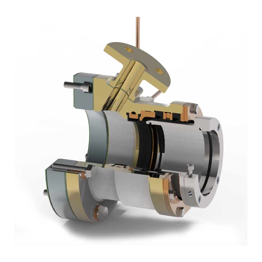
- Page 1 Pegasus Seals Deluxe 124 mm (Forw)
- Page 2 Eurekaweg 4 2991 ZB Barendrecht T +31 (0)180 629009 info@poseidon-bv.nl www.poseidon-bv.nl Installation & maintenance manual Order number Poseidon: 15000710 Vessel name / Number Serial number Pegasus seal Size :124mm Assembly drawing :26.124BRIB.400 BV type approval number : Certificate 21649/BO BV...
-
Page 3: Table Of Contents
1 Product description ..................5 1.1 Equipment checks and precautions before installation ........5 1.2 Limitations ……………………………………………………………………………………………………..…… .6 2 PEGASUS Deluxe inboard SEAL ..............7 2.1 General ....................7 2.2 Installation precautions ................7 2.3.1 Installation of a new Pegasus seal ............8 2.3.2 Installation of split seals …………………………………………………………………………………... -
Page 4: Introduction
This document remains the property of Poseidon Propulsion B.V. All rights reserved. This document or any part thereof may not be made public or disclosed, copied or otherwise reproduced or used in any form or by any means, without prior permission in writing from Poseidon Propulsion B.V. -
Page 5: Product Description
Goods should be examined on receipt to verify the contents and their condition. • Poseidon should be immediately advised of any damage or discrepancy in the range of products supplied. Damage which is clearly caused by handling in transit should be notified to the carrier. -
Page 6: Limitations
Eurekaweg 4 2991 ZB Barendrecht T +31 (0)180 629009 info@poseidon-bv.nl www.poseidon-bv.nl Limitations • When in use, the seals can absorb radial swing of the shaft. This depending on the shaft diameter, in combination with the actual shaft revs/min, this will vary. -
Page 7: Pegasus Deluxe Inboard Seal
Water circulation for the seals is particularity not required but is required to lubricate the water lubricated bearings in the tube. The Pegasus deluxe forward seal consists of a housing that contains 2 lip seals which run on a ceramic coated stainless steel liner. The intension is to prevent (sea)water coming into the vessel. -
Page 8: Installation Of A New Pegasus Seal
Mobil Unirex EP, Shell Albida RL The space between the seals is to be filled by approx 50%. Poseidon supplied a container with 300 cc grease with the seals. 9. Torque the mounting bolts up as per instructions in table below Torques in Nm for all StSt A4 - 70 bolts Friction coefficient taken = 0.20... - Page 9 Eurekaweg 4 2991 ZB Barendrecht T +31 (0)180 629009 info@poseidon-bv.nl www.poseidon-bv.nl Mounting procedure (item numbers given will correspond with the drawing) 1. When bringing the shaft in, slide the gaskets, the adaptor flange, the seal and gasket over the shaft.
- Page 10 Eurekaweg 4 2991 ZB Barendrecht T +31 (0)180 629009 info@poseidon-bv.nl www.poseidon-bv.nl 9. Place the wearing liner(item 2) in a way so that the radial lip seals (item 12) will run on the ceramic raceway. (sea fig. below) Taking in account the travel of the shaft due to propeller trust.
- Page 11 Eurekaweg 4 2991 ZB Barendrecht T +31 (0)180 629009 info@poseidon-bv.nl www.poseidon-bv.nl 2.3.2 Replacement Instructions for the seals by SPLIT seals with a propeller shaft in position. When complete new seal assemblies have been supplied, endless radial lip seals are mounted. When the seals need to be replaced while the vessel is in the water and or the shaftline is NOT removed, you can use split seals.
-
Page 12: Installation Of Split Seals
Eurekaweg 4 2991 ZB Barendrecht T +31 (0)180 629009 info@poseidon-bv.nl www.poseidon-bv.nl Figure 1 Figure 2 Figure 3 26. Place the Retaining ring (item 4) in place and fasten all bolt connections in reverse sequence of removal. Apply torques as stated on the table. -
Page 13: Overhauling / Replacement Pegasus Seal
Eurekaweg 4 2991 ZB Barendrecht T +31 (0)180 629009 info@poseidon-bv.nl www.poseidon-bv.nl 2.3.3 Replacement of the complete seal or overhaul. If the vessel is slipped and the shaft is dismounted and the seal as a complete item is to be dismounted for an overhaul than follow these instructions are to be followed up. -
Page 14: Alignment Of The Seal
Eurekaweg 4 2991 ZB Barendrecht T +31 (0)180 629009 info@poseidon-bv.nl www.poseidon-bv.nl 2.5 Alignment of the seal 1. To arrange this a the seal is equipped with 4 measure points. To take the measurements you need to use a Vernier caliper. - Page 15 Eurekaweg 4 2991 ZB Barendrecht T +31 (0)180 629009 info@poseidon-bv.nl www.poseidon-bv.nl Reading Top side Reading PB side Reading SB side Reading bottom Date When adjusting the seal, the bearing clearance is to be taken in account. The shaft, when not turning, rests in the bearing.
-
Page 16: Zero Wear-Down Measurements
Eurekaweg 4 2991 ZB Barendrecht T +31 (0)180 629009 info@poseidon-bv.nl www.poseidon-bv.nl 3 Zero wear-down measurements The wear-down of the forw bearing bush can be determined without removing the aft seal by carrying out a zero wear-down measurement. This measurement has to be carried out before launch. -
Page 17: Start-Up Procedure
Eurekaweg 4 2991 ZB Barendrecht T +31 (0)180 629009 info@poseidon-bv.nl www.poseidon-bv.nl 3 Start-up procedure Preparation and checks before use To put the propulsion installation into operation, see the relevant manuals from the supplier(s) of the propulsion installation. As regards the stern tube seals and bearings, the following steps must be taken: 1. -
Page 18: Periodic Maintenance
Eurekaweg 4 2991 ZB Barendrecht T +31 (0)180 629009 info@poseidon-bv.nl www.poseidon-bv.nl 4 Periodic maintenance Periodical Note Weekly Check temperature When rising check the alignment Montly Add 30 CC grease between the seals ½ yearly Check the alignment Each docking Measure the wear-... -
Page 19: Trouble Shouting
Eurekaweg 4 2991 ZB Barendrecht T +31 (0)180 629009 info@poseidon-bv.nl www.poseidon-bv.nl Trouble shooting Problem Cause / Solution Note Wearing liner will not go Ream the liner so a positive clearance of Shaft should on/over the shaft minimum 0.1 mm appears... -
Page 20: Service And Spare Parts
Eurekaweg 4 2991 ZB Barendrecht T +31 (0)180 629009 info@poseidon-bv.nl www.poseidon-bv.nl Service and spare parts We offer 3 spare parts kits; 1) Emergency kit, for each seal, existing out of; a. 2 pc Split seals. (item 12) b. Tube with grease This kit is to be used in emergency cases were usually the vessel stays in the water and the shaft is not demounted. - Page 21 Pegasus Seal 124 Bronze Inboard Damen SY SECTION A-A © Copyright 2007 by "Poseidon". More over this document is the property of "Poseidon". PCD O 6 pc. M16 This document, or any part there of, may not be made known be copied or be multiplied or in any other way be made use of without permission from "Poseidon".
Need help?
Do you have a question about the Pegasus Deluxe and is the answer not in the manual?
Questions and answers