Table of Contents
Advertisement
Quick Links
Advertisement
Table of Contents

Related Manuals for DV Power RMO25W


Summary of Contents for DV Power RMO25W
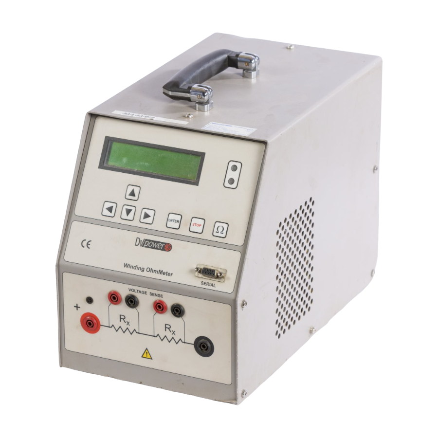
- Page 1 RMO25W W I N D I N G OHMMETER Manual BEKO OWER...
-
Page 2: Table Of Contents
Manufacturer Contact Information ....... . . 26 Manual Version: RMO25W. MV.04.20... -
Page 3: Introduction
2 Safety Instructions Before operating RMO25W, please carefully read the following safety instructions. It is not recommended that the RMO25W will be used (or even turned on) without the understanding of this manual. RMO25W should only be operated by trained and authorized personnel. -
Page 4: Designated Use
• The serial interface of RMO25W should only have external devices connected that meet the requirements for SELV equipment according to EN 60950 or IEC 60950. • When setting up RMO25W, make sure that the air slots of the test set remain unobstructed. -
Page 5: Functionality
RMO25W injects current with a voltage as high as 50 V at start. This ensures that the test is as short as possible, and that the desired test current is reached as soon as possible. - Page 6 An intrinsically safe discharge circuit, with indicator, dissipates the stored magnetic energy rapidly after the test. Cooling of RMO25W is supported by a built-in fan that is automatically activated every time a test is started from the Test menu. It continues running 5 minutes...
-
Page 7: Description
Press to measuring the resistance current value. Test parameters must be selected beforehand. Green LED • Lights continuously when RMO25W is turned on. • Flashes when a test can be started. • Flashes alternately with the red LED during a test. - Page 8 ENTER Pressing to cancel, returns you to the Curr menu. STOP 5.4 Setting RMO25W’s Time and Date To set RMO25W’s internal time and date, use the button, and then the LEFT buttons to select the Time menu. Figure 5-2: The Time menu showing RMO25W’s internal time and date...
-
Page 9: Getting Started
• the test object is disconnected or separated from its circuit in accordance with the national safety regulations and is properly grounded to protective earth, • RMO25W itself is properly grounded. To do so, connect the grounding screw on the back of RMO25W’s to PE using a grounding cable. - Page 10 RMO25W Getting Started 6.2 Setting the Measurement Parameters Turn on RMO25W with the power switch on the back of the test set. The display shows the Curr menu and the green LED lights up. Figure 6-2: Test current Memory position...
- Page 11 The Test menu displays the selected test current and its duration defined. If one of these values has to be changed, press to return to the Curr menu. STOP The flashing green LED indicates that RMO25W is now ready to start the test. Press the button to run a test. Ω...
- Page 12 Large transformers can require several minutes to discharge. When measeremet is complete RMO25W goes to the Res menu and starts current discharging. During current discharging, discharging LED lightens and beeper buzzes.
- Page 13 RMO25W Getting Started 6.6 Viewing the Test Results Once a test is finished, RMO25W automatically changes to the Res menu to display the test results. Test current Figure 6-8: Memory The Res menu position showing the test that holds results...
- Page 14 Getting Started 6.8 Printing the Test Results RMO25W stores up to 100 test results. They can be printed using the Print menu at memory positions 0 ... 99. Connect the RS 232 port of the RMO25W and the printer with a serial cable.
-
Page 15: Rmo Win Software
RMO25W RMOWin-W Software 7 RMOWin-W Software RMOWin-W is a Windows program for working with Winding OhmMeters RMO-W series. It enables the two-way communication RMO-W – PC over the serial port RS232. RMOWin-W supports the following functions: - Controlling and starting RMO-W when the tests are performed from the PC;... - Page 16 RMO25W RMOWin-W Software 7.3 Starting RMOWin-W Connect the RS 232 port of the RMO-W Winding OhmMeter and the PC, with a serial cable. Turn RMO-W on. Start RMOWin-W: - Click on ”Start”, - Click on ”Programs”, - Click on ''RMOWin-W’’, - Click on ‘’RMOWin-W’’,...
- Page 17 RMO25W RMOWin-W Software File Open Opening the file. Save As Saving the table in the working directory. Print Printing the active table. Exit Exiting the program. Download Data From RMO-W With this command the results from the internal RMO-W memory can be transferred to the PC.
- Page 18 RMO25W RMOWin-W Software Date The results that are filled in on the chosen date are going to be transferred to the PC. Date from – up to After choosing this option, a new window appears. It provides a choice of selecting a time-interval when the measurement was done.
- Page 19 RMO25W RMOWin-W Software Transfer After pressing this key, the selected results are going to be transferred from the internal RMO-W memory to the PC. Unless the user chooses some other option, all the results from the RMO-W memory will be transferred (the option All is a default).
- Page 20 RMO25W RMOWin-W Software Tools Clearing of table Erasing all the data from the main menu board. Choise of Comm Ports Choosing the otherPC serial port. This window provides a choice of the other active serial port to be used. After a choice has been made, the green led diode ”Communication”...
- Page 21 RMO25W RMOWin-W Software It is highly recommended to write the information in the columns ”Object”, ”Code” and ”Comments” for better systemization of the saved results. The new test moves the previous test results down so the first line represents the last performed test.
- Page 22 RMO25W RMOWin-W Software Interval Its purpose is selection of time interval for reading results from RMO-W to PC. Each time at the expiration of this interval from RMO-W to PC will be written last measured result. Press function “Interval”. The window, as shown bellow, will be opened.
-
Page 23: Error Messages
RMO25W Error Messages Error Messages Any operational error is indicated by a red LED and accompanied by an alarm. Furthermore, the display indicates an error status message. To stop the alarm buzzer, remove the status message on the display, and return to the Sing menu, press the button. - Page 24 In this case, wait for the test set to cool down and repeat the test. 8.3 Error Message "Malfunction" If this message is shown on the display, or if RMO25W cannot be operated anymore at all, a serious internal error occurred.
-
Page 25: Technical Data
RMO25W Technical Data Technical Data Mains Power Supply - Connection according to IEC/EN60320-1; UL498, CSA 22.2 - Voltage single phase 110 – 240 VAC, +10% – -15% - Frequency 50/60 Hz Output data - Test current 5mA – 25A DC - Tipycal Accuracy ±... -
Page 26: Accessories
RMO25W Technical Data, Accessories, Contact Information RS232 Interface RMO25W is equipped with an RS232 serial interface to connect to an external computer. not connected not connected not connected not connected Housing = shield not connected TXD (out) Transmit Data RXD (in)
Need help?
Do you have a question about the RMO25W and is the answer not in the manual?
Questions and answers