Table of Contents
Advertisement
Quick Links
Advertisement
Table of Contents

Related Manuals for DV Power RMO100A


Summary of Contents for DV Power RMO100A
- Page 1 RMO100A MICROOHMMETER Manual IBEKO P ower...
-
Page 2: Table Of Contents
8 Technical Data ..........................25 9 Accessories............................30 Manufacturer Contact Information ......................30 Manual Version: RMO100A MV.08.32 This Manual refers to the firmware version RO2-8.32 IBEKO Power AB 2011 This Manual is a publication of IBEKO Power AB, 181 33 Lidingö, Sweden. -
Page 3: Introduction
2 Safety Instructions Before operating RMO100A, please carefully read the following safety instructions. It is not recommended that the RMO100A will be used (or even turned on) without the understanding of this Manual. RMO100A should only be operated by trained and authorized personnel. -
Page 4: Designated Use
grounding. Any other use of the RMO100A than the ones mentioned above is to be considered improper and will not only invalidate all customer warranty claims but also exempt the manufacturer from its liability for repair or exchange. - Page 5 The display will not show this as an error message. During tests the high continued DC current will heat up the test set. To prevent RMO100A from overheating, duty cycles apply. The duty cycles depend on the used test current,...
-
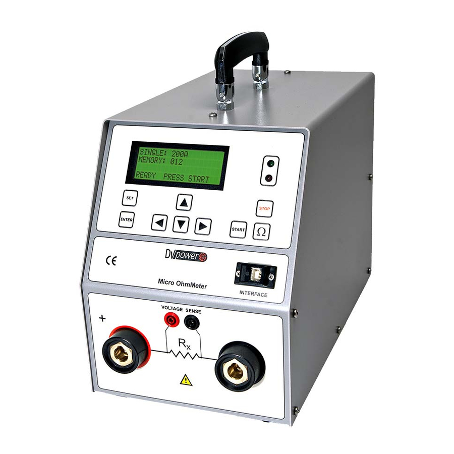
Page 6: Description
5.2 Rear Panel Components Connector for Power switch mains power supply I In this position, RMO100A is connected to the mains power supply. 0 In this position, RMO100A is separated from the mains power supply with both poles. Earth/ground connector... - Page 7 RMO100A Description 5.3 Settings To set RMO100A‟s language, date and time and Rmax press and hold button for 3 seconds to select Settings menu. Figure 5-1: The Settings menu Pressing to cancel, returns you to the Single menu. STOP Setting RMO100A’s Language To set RMO100A‟s language, use the...
- Page 8 UP/DOWN buttons select desired value between 1 µΩ and 9999 µΩ. First, initial value is 1000 µΩ (figure 5-4). When device is turned off and then turned on, RMO100A remembers last saved setting of Rmax value and status. Once these parameters are defined, press to change to the Settings menu.
-
Page 9: Getting Started
Connect the earth/ground lead first before doing any connections to the test object. Connect the mains lead to a mains outlet 100 V – 240 V AC and turn on RMO100A with the power switch on the test set. The first shown on the display is the name of the product followed by the instrument model type and the internal firmware version. - Page 10 The result can be recalled later by selecting that particular position number. Continuous Test Turn on RMO100A with the power switch on the test set. The display shows the Single menu. Go to Contin menu using button or four times button and then button.
- Page 11 Single menu. STOP The flashing green LED indicates that RMO100A is now ready to start the test. Press the START button to run a test. At the start of the test, a cable connection check is done. In case of e.g. a disconnection, an alarm is activated and the error message is shown on the display.
- Page 12 ± 0,25 % rdg ± 0,25 % FS 6.5 Viewing the Test Results Once a Single test is finished, RMO100A automatically changes to the Result menu to display the test results. For Continuous Test only the last performed test is shown.
- Page 13 If the Rmax menu is set to option , once a Single test is finished, RMO100A automatically changes to the Rmax to display the test results in case the measured resistance is equal or greater than maximum assigned value.
- Page 14 The red LED lights continuously indicating that assigned maximum value in Rmax menu is exceeded (or equaled). 6.6 Viewing Results of Previous Tests RMO100A stores up to 500 test results. They can be viewed using the Memory menu at memory positions 000 ... 499. Selecting a memory position on the Memory menu displays: •...
- Page 15 RMO100A Getting Started 6.8 Duty Cycles During tests, RMO100A generates a high DC current that heats up the test set. To prevent RMO100A from overheating, certain duty cycles apply depending on the used test current. Table 6-16: S i n g l e...
-
Page 16: Rmowin-R3A Software
- The transfer of the test parameters from the local RMO memory to the PC with the possibility of writing the notes on objects being measured and appropriate comments. Note: Using RMOWin-R3A software, a device RMO100A must be operated only from the RMOWin- R3A. - Page 17 The new test moves previous test results down so the first line represents the last performed test. The way to measure the resistance is described in details in the RMO100A Manual. If a user wants to analyze these results later, it should be saved on the hard disk. The table is going...
- Page 18 RMO100A Getting Started The illustration below depicts the main menu. File Open Opening the file. Save As Saving the table in the working directory. Print Printing the table. Exit Exiting the program. Download Data From RMO With this command the results from the internal RMO memory can be transferred to the PC. The transfer is possible only if the serial port RMO is connected, with the appropriate cable, to the PC and the green led diode ”Communication”...
- Page 19 RMO100A Getting Started Date The results that are filled in on the chosen date are going to be transferred to the PC. Date from – up to After choosing this option, a new window appears. It provides a choice of selecting a time-interval when the measurement was done.
- Page 20 RMO100A Getting Started Stop A user should press the button if for whatever reason he wants to interrupt a transfer. After STOP pressing this key all the choices are being erased and a user will return back to the main menu.
- Page 21 RMO100A Getting Started It is highly recommended to write the information in the columns ”Object”, ”Code” and ”Comments” for better systemization of the saved results. The new test moves the previous test results down so the first line represents the last performed test.
- Page 22 RMO100A Getting Started Measurement units It is possible to choose measurement units that will be displayed in saved Excel tables. Default measurement units are in A, mV and m. If data should be saved for the first time in current RMOWin- R3A session, the question is displayed for setting the measurement units.
- Page 23 The display will not show this as an error message. 8.2 Error Message "Open Connection" Figure 9-2: Disconnection of If one of RMO100A current cables ("+" or " -") the current to the test object is disconnected, on either cables and error...
- Page 24 In this case, wait for the test set to cool down and repeat the test. 8.6 Error Message "Malfunction" If this message is shown on the display, or if RMO100A cannot be operated anymore at all, a serious internal error occurred.
-
Page 25: Technical Data
UL 3111-1 CAN/CSA-C22.2 No 1010.1-92 9.7 Electromagnetic Compatibility (EMC) CE conformity EMC standard 89/336/EEC Emission EN 50081-2, EN 61000-3-2/3 Interference Immunity EN 50082-2 9.8 USB Interface RMO100A is equipped with an USB serial interface to connect to an external computer. -
Page 26: Accessories
RMO100A Error Messages 10 Accessories Recommended Current cables 2 x 5 m, 16 mm with battery clips Sense cables 2 x 5 m, 2,5 mm with alligator clips RMOWin-R3A PC software including USB cable Mains power cable Ground cable Transport bags... - Page 27 RMO100A Error Messages...
Need help?
Do you have a question about the RMO100A and is the answer not in the manual?
Questions and answers