
Related Manuals for IBA PQU-S


Summary of Contents for IBA PQU-S
- Page 1 Manual ibaPQU-S Power Quality Measurement Unit according to IEC61000-4-30 Ed. 3 Class A Manual Issue 1.3 Issue 1.0...
- Page 2 However, the information in this publication is updated regularly. Required cor- rections are contained in the following regulations or can be downloaded on the Internet. The current version is available for download on our web site www.iba-ag.com. Copyright notice ®...
-
Page 3: Table Of Contents
Manual Table of Contents About this manual ................... 6 Target group ....................7 Notations ....................... 7 Used symbols ....................8 Introduction ..................... 9 Modular concept ..................10 Measurements according to EN50160............11 Scope of delivery................... 11 Safety instructions ..................12 Proper use ....................12 Special safety instructions ................ - Page 4 First steps ....................31 10.1.1 Overview of the modules in ibaPDA ............38 10.2 Basic modules in I/O Manager ..............39 PQU-S – “General” tab ................39 10.2.1 PQU-S – “Analog” tab ................. 41 10.2.2 PQU-S – “Digital” tab .................. 41 10.2.3...
- Page 5 Manual 11.6 Connection diagram ..................97 11.6.1 Pin assignment voltage supply X14 ............. 97 11.6.2 Pin assignment digital inputs X5 ..............97 Accessories and related products ............... 98 Appendix ...................... 102 13.1 Calculating characteristic values ............... 102 13.1.1 RMS (Root Mean Square) ................. 102 13.1.2 Rectified value ...................
-
Page 6: About This Manual
Manual ibaPQU-S About this manual This manual describes the design, use and operation of the ibaPQU-S. For information on the design, use and operation of the I/O modules, please refer to the dedicated man- uals. Note The documentation of the ibaPQU-S system is included on the DVD that is part of the delivery. -
Page 7: Target Group
Manual Target group This manual addresses in particular the qualified professionals who are familiar with han- dling electrical and electronic modules as well as communication and measurement tech- nology. A person is regarded to as professional if he/she is capable of assessing safety and recognizing possible consequences and risks on the basis of his/her specialist train- ing, knowledge and experience and knowledge of the standard regulations. -
Page 8: Used Symbols
Manual ibaPQU-S Used symbols If safety instructions or other notes are used in this manual, they mean: Danger by an electric shock! The non-observance of this safety information may result in an imminent risk of death or severe injury: By an electric shock! Danger! The non-observance of this safety information may result in an imminent risk of death or severe injury! -
Page 9: Introduction
Manual Introduction ibaPQU-S is a modular system to measure power quality parameters using ibaPQU-S as central unit. ibaPQU-S measures raw values such as current and voltage in sync with the grid and calculates the characteristic values according to IEC 61000-4-30 Ed. 3 Class A. Charac- teristic values include: ... -
Page 10: Modular Concept
4 analog inputs are supported for the ibaPQU-S func- tion, voltage or current measurement configurable) All other I/O modules of the iba modular system are equally supported; however the signals are transmitted as raw values only. The raw signals and internally calculated characteristic values are sent to the ibaPDA data acquisition system via a bidirectional fiber optic connection for visualization and recording. -
Page 11: Measurements According To En50160
The scope of delivery comprises: ibaPQU-S unit Cover caps for FO cables, USB and Ethernet 16-pin connector with spring terminals (digital input channels) 2-pin connector with spring terminals (voltage supply) DVD (iba Software & Manuals) Issue 1.3... -
Page 12: Safety Instructions
Manual ibaPQU-S Safety instructions Proper use The device is an electrical apparatus. It is only allowed to use the device for the following applications: measurement data acquisition of voltage and current signals in energy grids applications with ibaPDA The device must only be used as described in chapter 11. -
Page 13: System Requirements
one ExpressCard(54/34) slot (notebook). For a list of suitable computer systems with desktop and industrial housings, please go to the iba homepage http://www.iba-ag.com. One FO input card type ibaFOB-D (firmware version D4 or higher): ibaFOB-io-D / ibaFOB-io-Dexp ... -
Page 14: Mounting, Connecting, Dismounting
Manual ibaPQU-S Mounting, connecting, dismounting Caution! Only work on the device when it is de-energized! Mounting 1. Mount the backplane on an appropriate construction. 2. Connect the ground terminal. 3. Attach the device into the left slot. Make sure that the guiding bolts on the rear side of the device are inserted into the corresponding holes on the backplane. -
Page 15: Connecting
Manual Connecting 1. Connect the measuring lines connected to the measuring objects to the I/O module inputs. Chapter Accessories and related products describes the connection princi- ples. 2. Use an ibaNet FO patch cable (duplex) to connect the device to the ibaPDA com- puter: ... -
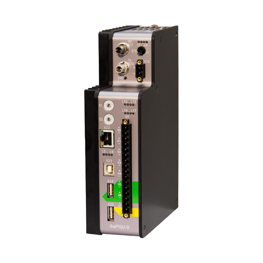
Page 16: Device Description
Manual ibaPQU-S Device description Views Operating state display L1...L4 ON/OFF switch S11 Connector for 24 V power supply X14 Display of digital inputs L10...L17 Connector for digital inputs X5 Fixing screws Displays L5...L8 Network interface X22 (no function) Rotary switches S1, S2 System function pushbutton S10 (no function) FO output socket (TX) X10 FO input socket (RX) X11... -
Page 17: Display Elements
Malfunction, internal device applications not running Hardware error Important note When the LED L4 indicates an error, please contact the iba Support. LEDs L5…L8 7.2.2 The LEDs L5 through L8 show status and progress when installing an update, see chap- ter 9 “Updates”. -
Page 18: Status Of Digital Inputs L10
S2 is not used (should be zero). Important note Unlike other iba devices that support the 32Mbit Flex protocol, it is allowed to operate only two ibaPQU-S systems in cascade configuration at one free 32Mbit Flex link of an ibaFOB card because of the high sampling rate of 10 - 40 kHz and the high data volume in the network channel of the Flex protocol. -
Page 19: Communication Interfaces
Communication interfaces 7.4.1 FO cable connections X10 and X11 The FO cables transmit the process data between the device and the connected iba systems. The 32Mbit Flex transfer protocol also allows configuration data to be trans- ferred via FO cable. -
Page 20: Debounce Filter
Manual ibaPQU-S 7.5.2 Debounce filter There are four debounce filters for each digital input. They can be chosen and configured independently of each other for each signal. The following filters are available: “Off” (no filter) “Stretch rising edge” ... - Page 21 Manual “Stretch both edges” With the first edge, the output signal (ochre) follows the original signal (blue) and keeps the logical level for the duration of the set debounce time. Subsequently, the channel is transparent again and waits for the next (rising or falling) edge. Debounce filter: “Stretch both edges”...
-
Page 22: Voltage Supply
Manual ibaPQU-S Voltage supply 7.6.1 Voltage supply X14 The external voltage supply is connected with a 2-pin connector. Caution! Only connect the device to an external voltage supply 24 V DC (±10 % unregulated)! Observe the correct polarity! 7.6.2 Backup voltage X30 The X30 terminal (bottom side of the unit) can be used to connect a backup voltage. -
Page 23: Measurement Principles And Measured Quantities
Manual Measurement principles and measured quantities To determine the power quality parameters, ibaPQU-S measures raw values such as currents and voltages in synch with the grid. The characteristic values relevant for power quality are calculated internally. Grid types The device is suitable for 1-phase grids, 3-phase grids without neutral conductor and 3-phase grids with neutral conductor (N) or protective earth (PE). -
Page 24: Signals And Calculated Characteristic Values
Manual ibaPQU-S Signals and calculated characteristic values The following table shows the required measured quantities depending on the grid type. Based on the measurements, all characteristic values are calculated which are needed to assess the power quality. Measured quantities 1-phase 3-phase without N/PE 3-phase with N/PE U12, U23, U31... - Page 25 Manual Characteristic Available Grid type Calculation Calculation time values (conductor) interval Half 10 s 3+N Phase Grid riod Reactive energy with sign Fundamental reactive energy Power factor Cos φ Positive sequence component Negative sequence component Zero sequence component Supply voltage unbalance (negative sequence component)
-
Page 26: System Integration
Manual ibaPQU-S System integration Figure 10: Measuring system with ibaPDA Acquisition of the raw values of voltage and current at the input modules Calculation of the characteristic values in ibaPQU-S Configuration of the modules, configuration of data recording, acquisition and visu- alization of the measured and calculated characteristic values in ibaPDA ... -
Page 27: Signal Filtering
Manual 8.5.2 Signal filtering To calculate the characteristic values, DIN EN 61000-4-7 dictates an anti-aliasing filter to suppress high-frequency interference that would corrupt the calculation of the har- monic components. A digital anti-aliasing filter with a cut-off frequency of approx. 3 kHz is implemented. - Page 28 Manual ibaPQU-S In this context, the range of the set signal (in the network definition) is irrelevant; the algorithm described above will always be used. For signals captured as raw signals, the range settings in ibaPDA take effect. Issue 1.3...
-
Page 29: Updates
Installing an update can take several minutes. Update via ibaPDA Open the ibaPDA I/O Manager and select the PQU-S module in the tree structure. Click the <Write firmware> button on the “Diagnostics” tab and select the “pqu_v[xx.yy.zzz].iba” update file. - Page 30 If a module is not yet known (i.e. it is more recent than the central unit's firmware version), it will be ignored and not displayed in ibaPDA. In this case, a new Update File has to be installed for the “overall release version”. Contact the iba Support. Issue 1.3...
-
Page 31: Configuration With Ibapda
1. Select “General” in the tree view and set the time base for data acquisition on the left to 1 ms. 2. Look for the corresponding link of the iba FOB-D card to which ibaPQU-S is con- nected in the I/O Manager. Right-click the link to open a submenu. Select “Autode- tect”. - Page 32 Manual ibaPQU-S 4. Right-click the connection (link) of the ibaFOB-io-D card to which the device is con- nected. 5. Select “Add module”. The list of available modules is displayed. Select “ibaPQU-S”. Subsequently, the device is displayed in the module tree. Hold the mouse button down and drag the device to the address (link 1 –...
- Page 33 The input modules and their configuration is described in the module manuals. 9. In the “PQU-S” basic module, you set the power frequency of your grid and specify a reference signal. One of the connected phases by which sampling is synchronized is used as the reference signal.
- Page 34 Manual ibaPQU-S The signals Un and In are optional input signals that do not have to be assigned. The option “Show line-to-line” allows the voltages U12, U23 and U31 to be provided also in a star system. If the signals are not assigned, ibaPQU-S calculates these values. If the signals are measured, the raw values serve as the basis for the other calculations.
- Page 35 Manual 14. Each submodule has its own time base; the default value should not be changed. The signal names in the submodules are already preset. They include the corre- sponding characteristic value, the measuring input and the measurement interval al- lowing it to be identified unambiguously in subsequent evaluations.
- Page 36 Manual ibaPQU-S chapter 10.3.9 “Basic submodule“ and following. Basic, values for each input: - RMS value, peak value, rectified value, frequency (measurement interval 200 ms and half period) - phase, form factor, crest factor (peak factor) (measurement interval 200 ms) ...
- Page 37 Manual Flicker severity, values per phase: inst Unbalance (asymmetry): values for voltages: - zero sequence unbalance - negative sequence unbalance - positive, negative, zero sequence component - phase angle of the positive sequence component, negative sequence compo- nent and zero sequence component values for currents: - positive, negative, zero sequence component - phase angle of the positive sequence component, negative sequence compo-...
-
Page 38: Overview Of The Modules In Ibapda
Manual ibaPQU-S 10.1.1 Overview of the modules in ibaPDA Module Characteristic values Measurement interval Half period EN50160: Power Frequency (reference signal, all voltage frequency inputs) EN50160: Slow RMS value supply voltage (all voltage inputs) variation EN50160: Fundamental frequency, THD up to 40th Harmonic harmonic, voltage... -
Page 39: Basic Modules In I/O Manager
Yellow = modules for additional measurements 10.2 Basic modules in I/O Manager PQU-S – “General” tab 10.2.1 Figure 12: PQU-S basic module – “General” tab Basic settings Module type Display of the module type (read only) Locked A locked module can only be modified by an authorized user. - Page 40 Manual ibaPQU-S Use name as prefix If “True” is selected, the module name is prefixed to the signal names of this mod- ule. Connection IP address IP address or host name of the ibaPQU-S device (read only). Auto enable/disable If this option is enabled and ibaPDA cannot establish a connection to this device when starting the measurement, it will disable this module and start the measure- ment without the module.
-
Page 41: Pqu-S - "Analog" Tab
The list shows the configured analog signals of the input modules and of all configured Grid modules and the analog status signals of ibaPQU-S with their actual values. Figure 13: PQU-S module – “Analog” tab PQU-S – “Digital” tab 10.2.3 The “Digital”... -
Page 42: Pqu-S - "Diagnostics" Tab
Write firmware This button allows running firmware updates. Select the update file “pqu_v[xx.yy.zzz].iba” in the browser and start the update by clicking <Ok>. Important note This process may take several minutes and must not be interrupted. After an update, the device will restart automatically. -
Page 43: Ibapqu-S - "General" Tab
Manual Reset to factory defaults Click this button to reset all settings to the factory defaults after confirming the fol- lowing prompt with <yes>. The following message is displayed and the device reinitializes automatically with the deleted I/O settings: Subsequently, run the “Autodetect”... -
Page 44: Ibapqu-S - "Digital" Tab
Basic settings Module type, Locked, Enabled, Name, Timebase, Use name as prefix see chapter 10.2.1 PQU-S – “General” tab. Module No. Logical module number for the unambiguous referencing of signals, e.g. in expres- sions and ibaAnalyzer. Is assigned by ibaPDA in ascending order, but can be changed by the user. -
Page 45: Ibapqu-S - "Status" Tab
Manual Debounce time (µs) Here, you can define the debounce time in µs Active Enabling/disabling the signal ibaPQU-S – “Status” tab 10.2.7 Figure 18: ibaPQU-S module – “Status” tab In the Status tab, you can enable status signals: Signal Meaning UDP data loss […]... -
Page 46: Diagnose - "General" Tab
Diagnose - “General” tab 10.2.8 In the “Diagnose” module, diagnosis signals are available. The module has to be added manually by right-clicking the “PQU-S” module and selecting “Diagnose” from the context menu. Figure 19: Diagnostics module - “General” tab Basic settings ... -
Page 47: Diagnose - "Digital" Tab
Manual Diagnose - “Digital” tab 10.2.9 In the “Digital” tab, you can activate diagnosis signals. Figure 20: Diagnostics module - “Digital” tab Signal Meaning Hardware state X[…] Module on slot X[…] is OK Hardware available X[…] Module on slot X[…] was detected and initialized properly Embedded application state Embedded application is currenty available... -
Page 48: Submodules To Calculate Characteristic Values
Grid module “General” tab Figure 21: Grid submodule – “General” tab Basic settings See PQU-S module, – “General” tab, chapter 10.2.1 Configuration Inputs Select the grid type from the dropdown menu. Depending on the grid type, the input measurement signals required for the grid type are displayed in the rows below. - Page 49 Manual Measured values In the dropdown menu, select which raw signals are available. Based on the selection, the inputs for voltages or currents are displayed or hidden. Show line-to-line This option is only available in a star system. It activates the additional inputs for U12, U23 and U31.
- Page 50 Manual ibaPQU-S Units The set units influence the calculated output values. If large input signals are combined in a calculation, e.g. kV and kA, this function produces understandable output values. Standard generation Enable currents If Enable currents = TRUE, all current values are calculated additionally. If “Only voltages”...
- Page 51 Manual Configure event settings In this dialog you can configure the settings for the single events such as voltage dip, voltage swell etc. The values preset are taken from the standard IEC 61000-4-30 Ed. 3 class A. Using the threshold values you can set the decision limit from which the corre- sponding event can be recognized.
-
Page 52: En50160 Submodule: Power Frequency
Manual ibaPQU-S The “EN50160” tab lists all signals calculated in the EN50160-compliant submodules. The message “Fully compliant” against a green background confirms compliance with the standard. If individual signals are disabled, the display changes to “Partially compli- ant” on a white background. This tab is only displayed if you have configured the EN50160 standard by clicking “Click to configure standards...”. - Page 53 Manual Basic settings See PQU-S module, “General” tab, chapter 10.2.1 Time base Each submodule has its own time base. The default setting should not be changed. Configuration The “Configuration” section shows the characteristic value that is determined by this module as well as the measurement interval.
-
Page 54: Submodule En50160: Supply Voltage Variation
Manual ibaPQU-S 10.3.3 Submodule EN50160: Supply voltage variation “General” tab Figure 25: EN50160 submodule: Supply voltage variation – “General” tab Basic settings See Power frequency submodule, “General” tab, chapter 10.3.2. Configuration The “Configuration” section shows the characteristic values determined by this module as well as the measurement interval. -
Page 55: En50160 Submodule: Flicker Severity
Manual contain the input channel, the function and the measurement interval. You can addi- tionally assign two comments by clicking the icon in the signal name field. Function, input, unit Displays the corresponding property Active Here you can enable or disable the signal. 10.3.4 EN50160 submodule: Flicker severity “General”... - Page 56 Manual ibaPQU-S “Analog” tab Figure 28: EN50160 submodule: Flicker severity – “Analog” tab Name The names are assigned by default. To allow an unambiguous identification, they contain the input channel, the characteristic value and the measurement interval. Function Calculation function used by ibaPQU-S.
-
Page 57: En50160 Submodule: Supply Voltage Unbalance
Manual 10.3.5 EN50160 submodule: Supply voltage unbalance “General” tab Figure 29: EN50160: Supply voltage unbalance– “General” tab Basic settings See Power frequency submodule, “General” tab, chapter 10.3.2 Configuration The “Configuration” section shows the characteristic values determined by this module as well as the measurement interval. - Page 58 Manual ibaPQU-S “Analog” tab Figure 30: EN50160 submodule: Supply voltage unbalance “Analog” tab Name The names are assigned by default. To allow an unambiguous identification, they contain the input channel, the characteristic value and the measurement interval. Function Calculation function used by ibaPQU-S.
-
Page 59: En50160 Submodule: Harmonic Voltage
Manual 10.3.6 EN50160 submodule: Harmonic voltage “General” tab Figure 31: EN50160 submodule: Harmonic voltage – “General” tab Important note The total number of Harmonic voltage and Spectrum submodules per ibaPQU must not exceed nine (9) to avoid overloading the system. Basic settings ... - Page 60 Manual ibaPQU-S “Analog” tab Figure 32: EN50160 submodule: Harmonic voltage – “Analog” tab The EN50160 submodule: Harmonic voltage calculates the harmonics 1 - 50 for each input channel plus the fundamental frequency and the total harmonic distortion (THD) in 10 minute measurement intervals. To calculate the THD, the EN50160 standard only takes harmonics 1-40 into account.
-
Page 61: En50160 Submodule: Mains Signalling Voltage
Manual 10.3.7 EN50160 submodule: Mains signalling voltage “General” tab Figure 33: EN50160 submodule: Mains signalling voltage – “General” tab Basic settings See Power frequency submodule, “General” tab, chapter 10.3.2 Configuration The “Configuration” section shows the characteristic values determined by this module as well as the measurement interval. - Page 62 Manual ibaPQU-S “Analog” tab Figure 34: EN50160 submodule: Mains signalling voltage – “Analog” tab The EN50160 submodule: Mains signalling voltage calculates the harmonics 1-50 and the interharmonics 1-50 for each input channel plus the fundamental frequency and the DC component, in 3 second measurement intervals. In the signal display, the signals are grouped by input.
-
Page 63: En50160 Submodule: Voltage Events
Manual 10.3.8 EN50160 submodule: Voltage events “General” tab Figure 35: EN50160 submodule: Voltage events – “General” tab Basic settings See Power frequency submodule, “General” tab, chapter 10.3.2 Configuration The “Configuration” section shows the characteristic values determined by this module as well as the measurement interval. -
Page 64: Basic Submodule
Manual ibaPQU-S The EN50160 submodule: Voltage events calculates the RMS value for each input chan- nel. Name The names are assigned by default. To allow an unambiguous identification, they contain the input channel, the characteristic value and the measurement interval. You can additionally assign two comments by clicking the icon in the signal name field. - Page 65 Manual “Analog” tab Figure 38: Basic submodule – “Analog” tab The Basic submodule captures the following characteristic values: Power frequency in 200 ms and half period measurement intervals, respectively For each input: RMS value, peak value, rectified value and frequency in 200 ms and half period measurement intervals ...
-
Page 66: Phasor Submodule
Manual ibaPQU-S 10.3.10 Phasor submodule “General” tab Figure 39: Phasor submodule – “General” tab Basic settings See Power frequency submodule, “General” tab, chapter 10.3.2 “Analog” tab Figure 40 : Phasor submodule – “Analog” tab Issue 1.3... - Page 67 Manual The Phasor submodule captures the following characteristic values for each input: RMS value, phase angle, frequency, measurement interval 200 ms In the signal display, the signals are grouped by input. Click the <+> sign before the group name to show the signals of a group. ...
- Page 68 Manual ibaPQU-S Display in the phasor diagram (phasor view) The voltage and current characteristics of the 3 phases can be visualized in a phasor diagram. Click the button in the ibaPDA toolbar to display the phasor diagram. Hold the mouse button down and drag the Phasor or Basic module from the signal tree on the left onto the display.
-
Page 69: Power Submodule
Manual 10.3.11 Power submodule “General” tab Figure 42: Power submodule – “General” tab Basic settings See Power frequency submodule, “General” tab, chapter 10.3.2 Configuration Enable distortion power Set this option to “True” if you want to activate the calculation of the distorsion power. - Page 70 Manual ibaPQU-S Depending on the AC/DC setting and the configured grid inputs, the Analog tab con- tains different characteristic values. AC/DC = DC Only active power, peak value and active energy are calculated. AC/DC = AC The following values are calculated for each phase: ...
-
Page 71: Spectrum Submodule
Manual Figure 44: Display in the phasor diagram 10.3.12 Spectrum submodule “General” tab Figure 45: Spectrum submodule – “General” tab Issue 1.3... - Page 72 Manual ibaPQU-S Important note The total number of Harmonic voltage and Spectrum submodules per ibaPQU must not exceed nine (9) to avoid overloading the system. Basic settings See Power frequency submodule, “General” tab, chapter 10.3.2 Configuration Input Select the input signal. ...
- Page 73 Manual Linear: General calculation formula with harmonic values without squaring. Square: General calculation formula with squared harmonics Psophometry up to 50th harmonic can be mapped using the type square and the normalization Hn. Since ibaPDA supports only one weighting factor per harmonic, the factors have to be multiplied first for psophometry and specified as total weighting factor per harmonic.
-
Page 74: Unbalance Submodule
Manual ibaPQU-S The Spectrum submodule calculates the absolute or relative harmonics 1-50 and the absolute or relative interharmonics 1-50 for the selected input channel plus the funda- mental frequency and the total harmonic distortion in the 200 ms measurement interval. ... - Page 75 Manual Figure 48: Unbalance submodule – “Analog” tab Signal Meaning Zero sequence unbalance Ratio of zero sequence component to positive sequence component in percent Negative sequence unbalance Ratio of negative sequence component to positive sequence component in percent Positive sequence component Percentage of symmetrical voltage vectors rotation direction Angle of the positive sequence component...
- Page 76 Manual ibaPQU-S Display in the phasor diagram The voltage unbalance can be visualized using the phasor diagram. Click the button on the ibaPDA toolbar to display the phasor diagram. Hold the mouse button down and drag the Unbalance module from the signal tree on the left onto the display.
-
Page 77: Flicker Severity Submodule
Manual 10.3.14 Flicker severity submodule “General” tab Figure 50: Flicker severity submodule – “General” tab Basic settings See Power frequency submodule, “General” tab, chapter 10.3.2 Configuration Lamp model To calculate the flicker, the lamp model to be used, 230V or 120V, has to be speci- fied. - Page 78 Manual ibaPQU-S “Analog” tab Figure 51: Flicker severity submodule – “Analog” tab Signal Meaning U# Instantaneous flicker severity ###V Pinst Value for the current flicker severity U# Flicker severity ###V Pst Short-term flicker level Pst U# Flicker severity ###V Plt Flicker value according to a cubic average of Pst values ...
-
Page 79: Aggregation Submodule
Manual 10.3.15 Aggregation submodule The Aggregation submodule is a freely configurable module in which the measurement interval and the characteristic values can be selected individually. The submodule name is assigned automatically by ibaPDA and is in accordance with the set measurement interval. - Page 80 Manual ibaPQU-S Configuration Update interval Select the measurement interval here. The following default intervals are available: 200 ms, 3 s, 10 s, 10 min or 2 h If you choose a default interval, the Unit and Amount fields will show the matching values and cannot be edited.
- Page 81 Manual “Analog” tab The display in the “Analog” tab depends on the settings in the “General” tab. In the following example, we selected “Auto” mode and the submodules “Basic” and “Power”. The characteristic values defined in the submodules are listed in the “Analog” tab.
- Page 82 Manual ibaPQU-S In the following example, the “Custom” mode was selected. The “Analog” tab shows no entries at first. Figure 54: Aggregation submodule – “Analog” tab Name You can select any name. You can additionally assign two comments by clicking the icon in the signal name field.
- Page 83 In addition to grids with 50 Hz and 60 Hz nominal frequency, ibaPQU-S also allows taking measurements in grids with a user-defined frequency. If a user-defined power frequency is set (in the PQU-S module), this will influence the length of the 200 ms measurement interval and the naming in the Aggregation submodule.
-
Page 84: Commutation Notches Submodule
Manual ibaPQU-S 10.3.16 Commutation notches submodule “General” tab Figure 55: Commutation notches submodule – “General” tab Basic settings See Power frequency submodule, “General” tab, chapter 10.3.2 Issue 1.3... -
Page 85: Events Submodule
Manual “Analog” tab Figure 56: Commutation notches submodule – “Analog” tab Signals: Depth of notch per phase in percent 10.3.17 Events submodule “General” tab Figure 57: Events submodule – “General” tab Basic settings See Power frequency submodule, “General” tab, chapter 10.3.2 You will find the configuration of the event limits in chapter 10.3.1 “Grid module”. - Page 86 Manual ibaPQU-S “Analog” tab Figure 58: Events submodule – “Analog” tab Signal Meaning Start How many seconds ago did the event start Duration Duration of the event Min/Max Minimum / maximum voltage value Delta Umax / Delta Uss Delta Umax: RMS value that was furthest from the floating average.
- Page 87 Manual “Digital” tab Figure 59: Events submodule – “Digital” tab The listed signals here are “True” as soon as the corresponding event is pending. Thus, a simple triggering to the pending event is possible. Issue 1.3...
-
Page 88: Technical Data
Manual ibaPQU-S Technical data 11.1 Main data Brief description Description ibaPQU-S Description Central unit for (iba modular system) Power Quality Moni- toring applications Order number 10.150000 Processor unit Processor 1.6 GHz Atom processor, dual core CPU Flash memory Solid-state drive... -
Page 89: Interfaces
Manual 11.2 Interfaces Interfaces ibaNet 32Mbit Flex (bidirectional) 2 ST plug connector (50/125 μm and 62.5/125 μm) for FO connections RX/TX Ethernet 10/100 Mbit/s 2x host, 1x device for service purposes 11.3 Digital inputs Digital inputs Number Version Galvanically isolated, protected against reverse polarity, single ended Debounce filter Debounce filter with 4 different settings... - Page 90 Manual ibaPQU-S Characteristic values Calculation time Grid type Half period 10/12 150/180 10 s 10 min Peak ...
-
Page 91: Dimensions
Manual 11.5 Dimensions ibaPQU-S (Dimensions in mm) Figure 60: Dimensions of ibaPQU-S (Dimensions in mm) Figure 61: Dimensions of ibaPQU-S with cables Issue 1.3... - Page 92 Manual ibaPQU-S Distance between two ibaPQU-S systems (Dimensions in mm) Figure 62: Minimum distance between two ibaPQU-S systems Issue 1.3...
- Page 93 Manual ibaPQU-S and backplane (Dimensions in mm) Figure 63: Dimensions of ibaPQU-S with backplane Issue 1.3...
- Page 94 Manual ibaPQU-S Mounting plate 19" (Dimensions in mm) Figure 64: Dimensions of 19" mounting plate Issue 1.3...
- Page 95 Manual Backplane ibaPADU-S-B4S with mounting angles (Dimensions in mm) Figure 65: Dimensions of ibaPADU-S-B4S with mounting angles Backplane ibaPADU-S-B1S for one central unit and one module (Dimensions in mm) Figure 66: Dimensions ibaPADU-S-B1S Issue 1.3...
- Page 96 Manual ibaPQU-S (Dimensions in mm) Figure 67: Dimensions of ibaPADU-S-B1S equipped Backplane ibaPADU-S-B for one central unit (Dimensions in mm) Figure 68: Dimensions ibaPADU-S-B Issue 1.3...
-
Page 97: Connection Diagram
Manual 11.6 Connection diagram 11.6.1 Pin assignment voltage supply X14 Connection + 24 V 11.6.2 Pin assignment digital inputs X5 Connection Digital input 00 + Digital input 00 - Digital input 01 + Digital input 01 - Digital input 02 + Digital input 02 - Digital input 03 + Digital input 03 -... -
Page 98: Accessories And Related Products
Manual ibaPQU-S Accessories and related products Backplane ibaPADU-S-B4S Order number 10.124000 Backplane module with rear installation option for 1 ibaPQU-S with up to 4 I/O modules W x H x D: 229 mm x 219 mm x 27 mm Fitting equipment included ibaPADU-S-B1S Order number 10.124002... - Page 99 Manual Mounting plate 19" for PADU-S modular Order number 10.124005 Mounting plate (483 mm/19") for up to 2 backplanes Mounting 1 ibaPQU-S centered or 2 ibaPQU-S left and right Fitting equipment included Module carrier for ibaPADU-S modular system Order number 10.124007 Module carrier for 1 backplane with ibaPADU-S- Terminal blocks...
- Page 100 Manual ibaPQU-S I/O modules iba modular system Product Order No. Note ibaMS3xAI-1A 10.124600 3 analog inputs, 1 A AC ibaMS3xAI-5A 10.124610 3 analog inputs, 5 A AC ibaMS3xAI-1A/100A 10.124620 3 analog inputs, 1 A AC/100 A DC ibaMS4xAI-380VAC 10.124521 4 analog inputs, 380 V AC ibaMS8xAI-110VAC 10.124500...
- Page 101 For up to 1024 signals ibaPDA-V6-2048 30.620480 For up to 2048 signals ibaAnalyzer 33.010400 Offline and online analysis software with free license for analyzing *.dat files generated by licensed iba software. For further accessories, visit our online catalog at www.iba-ag.com. Issue 1.3...
-
Page 102: Appendix
Manual ibaPQU-S Appendix 13.1 Calculating characteristic values The characteristic values are calculated as follows: 13.1.1 RMS (Root Mean Square) 13.1.2 Rectified value 13.1.3 Peak value 13.1.4 Form factor 13.1.5 Crest factor 13.1.6 Frequency 13.1.7 Harmonics, interharmonics, phase angle Calculation with FFT algorithm 13.1.8 THD (Total Harmonic Distorsion) Issue 1.3... -
Page 103: Flicker
Manual 13.1.9 Flicker Short term Flicker algorithm Long term 13.1.10 Power / Energy Two conductors / per phase Active power Apparent power Total reactive power Fundamental reactive power Distorsion reactive power Power factor Cos φ Issue 1.3... - Page 104 Manual ibaPQU-S Three conductors Active power Apparent power Total reactive power Fundamental reactive power Distorsion reactive power Power factor Cos φ Pro Phase: Total grid: no calculation possible Issue 1.3...
- Page 105 Manual Four conductors Active power Apparent power Total reactive power Fundamental reactive power Distorsion reactive power Per phase: Total grid: Power factor Cos φ Per phase: Total grid: no calculation possible Neutral conductor current (if physically not available) Issue 1.3...
-
Page 106: Voltage Balance / Unbalance
Manual ibaPQU-S 13.1.11 Voltage balance / Unbalance Figure 69: Example graph from ibaPDA (high asymmetry!) In a symmetrical grid the arrows of the respective phase are located directly over each other. Name Meaning RMS value of the phase Percentage of the positive sequence component Percentage of the negative sequence component Percentage of the zero sequence component Positive sequence component... -
Page 107: Interference Factor
Manual The voltages specified here are complex numbers and consist of an amount and an angle. Negative sequence unbalance Zero sequence unbalance 13.1.12 Interference factor TIF/THFF : Nominal power system frequency (50 Hz or 60 Hz) Factor : Weighting factor for harmonic Various methods are available for normalization of Issue 1.3... -
Page 108: Commutation Notches
Manual ibaPQU-S 13.1.13 Commutation notches Commutation notch = voltage drop = peak value of the fundamental wave of the rated voltage Issue 1.3... -
Page 109: Events
Manual 13.1.14 Events Voltage dip Signal Meaning Voltage dip (digital) Active, if the half period RMS value of at least one phase is lower than the limit. Current time – start_time, in seconds, while the Voltage dip Start event is running. Voltage dip Duration Previous duration of events, in seconds, while the event is running. - Page 110 Manual ibaPQU-S Mains signalling Signal Meaning Mains signalling voltage (digital) Active, if the RMS value of the mains signalling voltage on at least one phase is higher than the limit set. Current_time – start_time, in seconds, while the Mains signalling voltage Start event is running Mains signalling voltage Duration Previous duration of events, in seconds, while the...
-
Page 111: Connection Examples
Manual 13.2 Connection examples The examples mentioned here refer to a grid with 230 V and 50 Hz. Furthermore, the consumers to be measured are directly connected to the ibaPQU-S system. If the values voltage and current to be measured are higher, appropriate instrument transformers need to be used. -
Page 112: Delta Connection
Manual ibaPQU-S 13.2.3 Delta connection Figure 72: Delta connection direct connection 13.2.4 Connection with instrument transformers It is important that the instrument transformers are Open Loop transformers. This means that a sinus signal on the primary side also needs to exist on the secondary side. The instrument transformers also need to offer a broadband frequency transmission in order to capture harmonics or interharmonics up to the 50th harmonic. - Page 113 Manual Figure 74: Example of 1-phase measuring with a Rogowski coil or a current clamp Issue 1.3...
-
Page 114: Index
Manual ibaPQU-S Index IP address via FO backplane Measurements Calculated characteristic values 24, 78 Current measurement Nominal frequency Debounce filter configure in ibaPDA Phasor diagram 66, 69 Digital signals Pin assignment configure in ibaPDA digital inputs DIN EN 50160 11, 34 Power supply Display digital inputs... -
Page 115: Certificate
Manual Certificate Issue 1.3... -
Page 116: Support And Contact
+49 911 97282-33 E-Mail: iba@iba-ag.com Kontakt: Mr. Harald Opel Shipping address iba AG Gebhardtstr. 10 90762 Fürth Germany Regional and worldwide For contact data of your regional iba office or representative please refer to our web site www.iba-ag.com. Issue 1.3...
Need help?
Do you have a question about the PQU-S and is the answer not in the manual?
Questions and answers