Table of Contents
Advertisement
Advertisement
Table of Contents

Related Manuals for IBA BM-PN


Summary of Contents for IBA BM-PN
- Page 1 ibaBM-PN PROFINET Busmonitor Manual Issue 1.9...
- Page 2 Required corrections are contained in the following regulations or can be down- loaded on the Internet. The current version is available for download on our web site http://www.iba-ag.com. Windows is a label and registered trademark of the Microsoft Corporation. Other prod- ®...
-
Page 3: Table Of Contents
ibaBM-PN Manual Table of contents About this manual ................... 5 Target group ....................5 Notations ....................... 5 Used symbols ....................6 Introduction ..................... 7 Scope of delivery..................... 9 Safety instructions ..................10 Designated use ................... 10 Special safety instructions ................10 System requirements .................. - Page 4 Manual ibaBM-PN Configuration with ibaPDA ................24 First steps for the configuration in ibaPDA........... 24 9.1.1 Configuration as active device..............24 9.1.2 Configuration as sniffer ................27 9.1.3 Configuration as sniffer at the SINAMICS Link ..........28 Modules in the I/O Manager ................ 30 9.2.1 "ibaBM-PN“...
-
Page 5: About This Manual
ibaBM-PN Manual About this manual This manual describes the construction, the use and the operation of the ibaBM-PN de- vice. Target group This manual addresses in particular the qualified professionals who are familiar with han- dling electrical and electronic modules as well as communication and measurement tech- nology. -
Page 6: Used Symbols
Manual ibaBM-PN Used symbols If safety instructions or other notes are used in this manual, they mean: The non-observance of this safety information may result in an imminent risk of death or severe injury: By an electric shock! Due to the improper handling of software products which are coupled to input and output procedures with control function! The non-observance of this safety information may result in a potential risk of death or severe injury! -
Page 7: Introduction
ibaBM-PN Manual Introduction The PROFINET bus monitor ibaBM-PN is a device for acquiring the cyclical data ex- change between the PROFINET (PN) controller and PN devices. The device supports PROFINET IO specification V2.35 and can be integrated in an existing PROFINET net- work with one or more standard PN controllers. - Page 8 Manual ibaBM-PN 8 devices, 32 words, 500 µs Monitor interface for connecting a network analysis tool Supports PROFINET IO specification V2.35 RT (Real Time) and IRT communication (Isochronous Real Time) possible, up to 250 µs Data acquisition with ibaPDA ...
-
Page 9: Scope Of Delivery
After having unpacked the delivery, please check if it is complete and intact. The following components are included in delivery: ibaBM-PN device ibaBM-PN manual Patch cable short DVD “iba Software & Manuals" with the following content: GSDML files Application examples Issue 1.9... -
Page 10: Safety Instructions
Measurement data acquisition and measurement data analysis Automation of industrial plants Applications of iba software products (e.g ibaPDA) and iba hardware products The device may only be used as defined in the "Technical Data" chapter. Special safety instructions... -
Page 11: System Requirements
Multicore CPU 2 GHz, 2048 MB RAM, 100 GB HDD, or higher At least one free PCI/PCIe slot (computer) On our homepage http://www.iba-ag.com you find suitable computer systems with desktop and industry housing. At least one FO input and output card of the ibaFOB-D, ibaFOB-Dexp, ibaFOB-io- ExpressCard type or ibaFOB-io-USB adapter ... -
Page 12: Mounting And Dismounting
Manual ibaBM-PN Mounting and dismounting Mounting 1. Insert the DIN rail clip on the rear side of the device on top in the DIN rail, press the device down/back and let the DIN rail lock. 2. If there is the provision in the plant that the device has to be grounded, then connect the device to the ground (shield connector X29). -
Page 13: Device Description
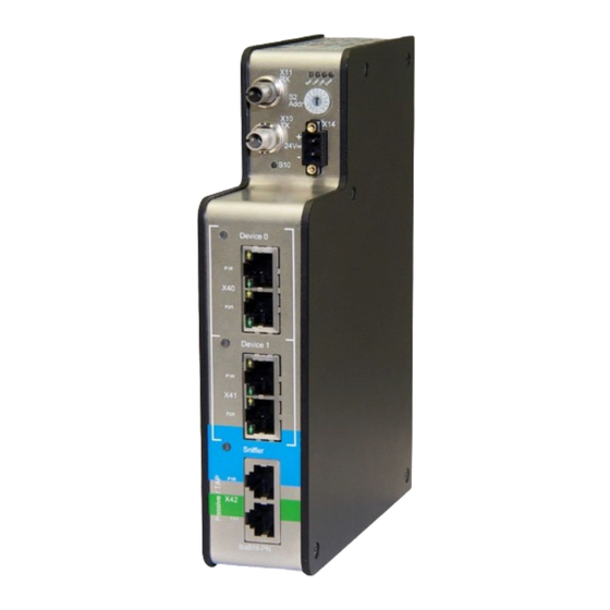
ibaBM-PN Manual Device description Device view Operating state display Rotary switch S2 Fiber optic input (RX) X11 Voltage supply X14 Fiber optic output (TX) X10 Push button S10 (Reset) PROFINET device 0 X40 (2-port switch) PROFINET device 1 X41 (2-port switch) TAP interface X42 (sniffer) Figure 1: Front view... -
Page 14: Indicating Elements
Manual ibaBM-PN Indicating elements On the device, colored light diodes (LED) show the operating status of the device. Operating state State Description Blinking Ready for operation, power supply connected (green) Blinking Update mode or reset to default settings rapidly (S10 push button) Boot phase Blinking TCP/UDP/IP telegram detected via FO... -
Page 15: Operating Elements, Connections
ibaBM-PN Manual Operating elements, connections 7.3.1 FO connections X10 (TX) and X11 (RX) X11 (RX): FO receiving interface X10 (TX): FO sending interface On the ibaPDA system, a FO input/output card of the ibaFOB-D or ibaFOB-Dexp type has to be installed for receiving and sending the data. Maximum distance of fiber optic connections The maximum distance of fiber optic connections between 2 devices depends on various influencing factors. -
Page 16: Rotary Switch S2
Manual ibaBM-PN 7.3.4 Rotary switch S2 With the 32Mbit Flex protocol, up to 15 devices can be connected in a ring topology. The devices are addressed using the rotary switch S2. Device number in the cascade Position of the rotary switch Not permitted 1. -
Page 17: System Integration
ibaBM-PN Manual System integration The ibaBM-PN device can be integrated into an automation system in many different ways. Data acquisition with 1 device Figure 3: Data acquisition with 1 device In the example above, one PROFINET device of the ibaBM-PN is used by a PROFINET controller. -
Page 18: Data Acquisition As Shared Device
Manual ibaBM-PN Figure 5: Data acquisition with 2 devices and 2 controllers In the example above, the two ibaBM-PN PROFINET devices are used by different PROFINET controllers. For this purpose, each device has to be entered via the GSDML file in the configuration of the respective PROFINET controller. The installation location within the PROFINET line is not relevant. -
Page 19: Data Acquisition With Tap / Sniffer
ibaBM-PN Manual Data acquisition with TAP / Sniffer Figure 7: Data acqusition with TAP / Sniffer In the above example, the TAP interface is used for aquiring and analyzing the trans- ferred data without interferences. It does not have to be integrated into the configuration of the PROFINET controller. -
Page 20: Data Acquisition In Mixed Operation
Manual ibaBM-PN Data acquisition in mixed operation Figure 8: Data acquisition with 2 devices and TAP/Sniffer With the example above, we show one possible scenario how to combine the different versions. Here, we show the data acquisition via TAP/Sniffer and both PROFINET devices. The installation location within the PROFINET line is relevant regarding the TAP inter- face. -
Page 21: Sinamics Link Participant
ibaBM-PN Manual In this configuration, ibaBM-PN can be integrated into the SINAMICS Link at any point between two control units and read data. 8.7.2 1 SINAMICS Link participant Figure 10: Data acquisition as Sniffer at SINAMICS Link with only one participant To enable data acquisition at the SINAMICS Link with only one controller, one of the two PROFINET devices can be switched to the SINAMICS emulation mode. -
Page 22: 32Mbit Flex Protocol And Ibafob-D Network
The ibaNet 32Mbit Flex protocol (referred to as "Flex protocol") is a manufacturer-specific data transfer protocol by iba AG. This protocol serves to transfer measurement and con- figuration data via FO connections between different iba devices. The PC cards of the ibaFOB-D/ibaFOB-Dexp and ibaFOB-io-ExpressCard series as well as some devices for data acquisition support this protocol. -
Page 23: Ring Topology
In the ring, also other 32Mbit Flex capable iba devices can be integrated, e. g. ibaPADU- S-CM like in the example above. The devices in the ring are addressed using the rotary switch for the device address (rotary switch S2 for ibaBM-PN). -
Page 24: Configuration With Ibapda
Manual ibaBM-PN Configuration with ibaPDA First steps for the configuration in ibaPDA 9.1.1 Configuration as active device With the following instructions, you integrate the ibaBM-PN device stepwise as an active device in ibaPDA and configure the measurement signals. 1. Connect the device to a voltage source and switch on the device (see chapter 7.3.2). 2. - Page 25 ibaBM-PN Manual According to the selected Flex address (switch S2), the device has to be dragged to the correct address position using drag & drop. 7. Please define on the "General" tab the parameters of ibaBM-PN. The following pa- rameters are important: ...
- Page 26 Manual ibaBM-PN 8. If you want to connect the device with one or two devices to PROFINET, you first have to configure the controller (see chapter 10.1). 9. Add a module under the ibaBM-PN device. Click with the right mouse-button on the ibaBM-PN device and select "Add module"...
-
Page 27: Configuration As Sniffer
ibaBM-PN Manual By clicking on the header of a column, all the settings in the rows below are filled in au- tomatically. Example: If you want to configure another data type, beginning with a specific row, then change the data type in the first concerned row. Now, click on the “Data type“ header. In all the rows below, the data type is changed automatically. -
Page 28: Configuration As Sniffer At The Sinamics Link
Manual ibaBM-PN 2. Now, enter the “No analog signals“ and “No digital signals“ in the “General” tab of the module. The default setting is 32; a maximum of 1000 analog and 1000 digital signals can be assigned per module. This value determines the length of the signal tables on the “Analog“... - Page 29 ibaBM-PN Manual 2. Now, enter the “No analog signals“ and “No digital signals“ in the “General” tab of the module. The default setting is 16 analog and 1 digital signal; a maximum of 1000 analog and 1000 digital signals can be assigned per module. This value determines the length of the signal tables on the “Analog“...
-
Page 30: Modules In The I/O Manager
Manual ibaBM-PN Modules in the I/O Manager If you want to use ibaBM-PN with ibaPDA, you have to configure the device in the ibaPDA I/O Manager. Use the step-by-step procedure described in chapter 9.1. In the following paragraphs, we describe the available modules. 9.2.1 "ibaBM-PN“... - Page 31 ibaBM-PN Manual 9.2.1.1 "General“ tab Figure 14: "ibaBM-PN“ module – “General“ tab Basic settings Module type (only read) Display of the module type Locked A module can be locked in order to prevent accidental or unauthorized changes in the module settings.
- Page 32 Manual ibaBM-PN 9.2.1.2 “Analog“ tab If analog signals have been configured in the modules „Device slot“ and the configuration has been transferred to ibaBM-PN, you will see here an overview of all acquired analog signals with an online overview of the currently acquired values. Figure 15: “ibaBM-PN“...
- Page 33 Firg. 17: “ibaBM-PN“ module – “Diagnostics“ tab Firmware update With the <Write firmware> button, you can install firmware updates. Please select the update file „bmpn_v[xx.yy.zzz].iba“ in the browser and start the update with <OK>. Important note This procedure might take some minutes and must not be interrupted. As soon as the process has been finished, the device restarts automatically.
- Page 34 Manual ibaBM-PN Finally, the following message is shown: Enter license code The button <Enter license code> opens a dialog in which you enter the numeric key for activation Note Licenses are always bound to a device, i.e. they are not portable between devices. ...
-
Page 35: Device 0/1" Node
ibaBM-PN Manual 9.2.2 „Device 0/1“ node The „Device 0/1“ node shows information about the respective internal PROFINET de- vice: the current status, the PROFINET device name, the MAC address and the slot configuration. Figure 18: “Device 0/1“ node Status, Device mode, Device name, MAC address Display of current states/values ... -
Page 36: Device Slot" Module
Manual ibaBM-PN Application Relation Each PN controller can be connected to one or more slots, but each slot is as- signed to only one PN controller. The „Application relation“ column shows the index and the IP address of the connected PN controller for that slot. If the PROFINET device is operated as S2 device, the index and IP addresses of both PN controllers are displayed in the column. - Page 37 ibaBM-PN Manual Advanced No. analog signals Defining the number of analog signals for this module (max. 252). No. digital signals Defining the number of analog signals for this module (max. 1024). PROFINET Device Assigning the module to device 0 or 1 ...
- Page 38 Manual ibaBM-PN Example For a SIMATIC ET200 AI/AO module, a +/-10V signal with a value range of -27648 … 27648 (equals -10V … +10V) is transferred. Within the control program, the transferred value has a physical meaning (e. g. temperature 50°C … 500°C). You can choose by Gain/Offset a conversion of the value.
- Page 39 ibaBM-PN Manual More columns can be displayed or hidden, using the context menu (right mouse-click on the header). 9.2.3.3 “Digital“ tab Figure 21: “Device slot” module – “Digital“ tab Enter here the digital signals you want to record in sequential order. The columns in the signal list have the following meaning: ...
-
Page 40: Device Slot Decoder" Module
Manual ibaBM-PN 9.2.4 “Device slot decoder“ module The module „Device slot decoder“ is only available underneath a device node. The "Device slot decoder" module is suited for acquiring large amounts of digital signals of a device. The signals are sent as words from a controller to a device. 9.2.4.1 “General“... - Page 41 ibaBM-PN Manual 9.2.4.2 “Digital” tab The signals are declared in two steps. First of all, the words you want to acquire as source for the digital signals have to be defined in sequential order. Figure 23: “Device slot decoder” module – “Digital“ tab Enter here word signals, which contain the digital signals in sequential order.
-
Page 42: Tap" Node
Manual ibaBM-PN Note Only the activated digital signals are considered when counting the number of licensed signals, hence no additional signal for the source word. ibaBM-PN only acquires one analog value, which is then decoded by ibaPDA. Thus, the range of analog values is used in ibaBM-PN for acquiring large amounts of digital sig- nals. - Page 43 ibaBM-PN Manual the time period since the last time they were saved. Only data of configured and en- abled devices will be saved. Controllers, Devices, Subslots, CRs Number of the used, configured and maximum allowed controllers, devices, sub- slots or CRs. ...
- Page 44 Manual ibaBM-PN Figure 26: „TAP“ node Device status and configuration Application relations (AR) Displays the current values A tab is displayed per detected application relation, this appears when e.g. „shared devices“ is used. Status, controller MAC, type, creation time Displays the current values ...
-
Page 45: Sniffer" Module
ibaBM-PN Manual 9.2.6 „Sniffer“ module The sniffer module is only available underneath a TAP node. 9.2.6.1 „General“ tab Figure 27: „Sniffer“ module – „General“ tab Basic settings Module type, Locked, Enabled, Name, Timebase, Use name as prefix see chapter 9.2.1.1. ... - Page 46 Manual ibaBM-PN 9.2.6.2 „Analog“ tab Figure 28: „Sniffer“ module – „Analog“ tab Enter the analog signals you want to record in sequential order. The columns of the signal list have the following meaning: Name You can enter a signal name and additional two comments when clicking the symbol in the signal name field.
- Page 47 ibaBM-PN Manual 9.2.6.3 „Digital“ tab Figure 29: „Sniffer“ module – „Digital“ tab Enter here the digital signals you want to record in sequential order. The columns of the signal list have the following meaning: Name You can enter a signal name and additional two comments when clicking the symbol in the signal name field.
-
Page 48: Sniffer Decoder" Module
Manual ibaBM-PN 9.2.7 „Sniffer decoder“ module The “Sniffer decoder” module is only available underneath a TAP node. The "Sniffer decoder" module is suited for acquiring large amounts of digital signals in the form of words on PROFINET (e.g. status words of drives). 9.2.7.1 „General“... - Page 49 ibaBM-PN Manual 9.2.7.2 “Digital” tab The signals are declared in two steps. First of all, the words you want to acquire as source for the digital signals have to be defined in sequential order. Figure 31: “Sniffer decoder” module – “Digital“ tab Enter here word signals, which contain the digital signals in sequential order.
- Page 50 Manual ibaBM-PN Name Assign a meaningful name to the individual digital signals. Active Only when this option is selected, the signal is acquired and also considered when checking the number of licensed signals. Note Only the activated digital signals are considered when counting the number of licensed signals, hence no additional signal for the source word.
-
Page 51: Sniffer Silink" Module
ibaBM-PN Manual 9.2.8 „Sniffer SiLink“ module The “Sniffer SiLink” module is only available underneath a TAP node. Each SINAMICS controller corresponds to one module "Sniffer SiLink" in ibaPDA. Each controller is iden- tified by its own device number (ID). This is defined in the SINAMICS project engineering. 9.2.8.1 „General“... - Page 52 Manual ibaBM-PN 9.2.8.2 „Analog“ tab Figure 33: „Sniffer SiLink“ module – „Analog“ tab Enter the analog signals you want to record in sequential order. The columns of the signal list have the following meaning: Name You can enter a signal name and additional two comments when clicking the symbol in the name field.
- Page 53 ibaBM-PN Manual 9.2.8.3 “Digtal“ tab Figure 34: „Sniffer SiLink“ module – „Digital“ tab Name Default name: “Status”. You can enter a two comments when clicking the sym- bol. Address Byte address of the signal Bit no. Bit number within with the bytes specified in the address ...
- Page 54 Manual ibaBM-PN Click on the <Change mode> button and confirm the following warning message. In the following dialog select the device mode “SINAMICS emulation” and confirm with <OK>. The enabled mode is displayed in the Device mode field. Port 1 of the PROFINET device with enabled SINAMICS emulation mode must be con- nected to a port of the TAP interface with a patch cable.
- Page 55 ibaBM-PN Manual 9.2.8.5 Notes on the exchange of an ibaBM-SiLink bus monitor A bus monitor ibaBM-SiLink can be replaced in a SINAMICS Link by ibaBM-PN in a function-compatible way. The following conditions apply: The installation location within the SINAMICS Link is not relevant. The TAP inter- face must always be integrated in a linear structure.
-
Page 56: Bus Diagnostics" Module
Manual ibaBM-PN 9.2.9 “Bus diagnostics” module Predefined diagnostic signals to the connected PROFINET network can be acquired as signals in ibaPDA with the "Bus diagnostics" module. For the meaning of the signals see chapter 9.2.5. 9.2.9.1 “General” tab Figure 37: “Bus diagnostics” module, “General” tab ... -
Page 57: Device Diagnostics" Module
ibaBM-PN Manual Gain / Offset Gradient (Gain) and y axis intercept (Offset) of a linear equation. You can convert a standardized and unitless transmitted value into a physical value. Active Only when this option is selected, the signal is acquired and also considered when checking the number of licensed signals. - Page 58 Manual ibaBM-PN 9.2.10.2 “Analog” tab Figure 40: “Device diagnostics” module, “Analog” tab Name The names are predefined. You can enter additional two comments when clicking symbol in the signal name field. Unit Physical unit of the signal. Gain / Offset Gradient (Gain) and y axis intercept (Offset) of a linear equation.
-
Page 59: Configuring Outputs
ibaBM-PN Manual Configuring outputs Outputs can be used to send signals from ibaPDA to a PROFINET controller via a device slot. The device must have at least one slot with input data for this purpose. This must be taken into account in the controller configuration. For configuring the outputs, select the "Outputs"... - Page 60 Manual ibaBM-PN Expression Enter here an expression which defines the output signal. The Intellisense function supplies you with automatic support for creating an expression. Optionally, you can also open the expression builder by clicking on the symbol. The expression builder will help you in creating an expression. Other documentation For more information about the function of the expression builder and the available functions, please refer to the ibaPDA manual.
- Page 61 ibaBM-PN Manual Data type Data type of the signal Active Please activate here the signal, which is to be output. Output of digital values Define the digital values you want to output on the "Digital" tab. The procedure is identical to the procedure for the analog values. Additionally to the "Address"...
-
Page 62: Calculation Of The Telegram Size With 32Mbit Flex
Manual ibaBM-PN Calculation of the telegram size with 32Mbit Flex The data size per participant is dynamically allocated in a 32Mbit Flex ring. The data size is calculated by ibaPDA and it depends on the configured number of analog and digital signals and the smallest configured timebase in the ring. - Page 63 ibaBM-PN Manual Reserved bandwidth for Ethernet communication The Ethernet channel (address 0) is used to transmit configuration data. If many devices are configured with a lot of signals, it may happen, that only the minimum size of 1 kB/s is reserved for Ethernet communication. This is not sufficient in many cases and may cause, that the configuration data are transmitted only slowly or cannot be transmitted at all.
-
Page 64: Profinet Engineering
1. Install the GSDML file. The ibaBM-PN will be integrated in the hardware catalog in PROFINET IO -> General -> iba AG -> iba BM -> ibaBM-PN busmonitor. 2. Insert the ibaBM-PN device in the configuration of the PROFINET controller. -
Page 65: Operation As S2 Device
ibaBM-PN Manual Maximum slot configuration The following configuration can be used to exploit the maximum device size of 1440 bytes: 5x 252 bytes + 170 bytes = 1430 bytes In addition, 6 status bytes (1 byte per slot) + 4 global diagnostic bytes are taken into ac- count by the system, the result is the maximum 1440 bytes. - Page 66 Manual ibaBM-PN The following technical restrictions are to be taken into consideration: To detect a PROFINET device in the network, the telegram interexchange during connection set-up (CPU restart, cable reconnection) must be recorded. The configuration data from once in the network detected and from Sniffer modules referenced PROFINET devices is saved.
-
Page 67: Technical Data
Manual Technical data 11.1 Main data Manufacturer iba AG, Germany Order no. 13.120000 Description PROFINET bus monitor PROFINET interfaces Number 3 (2 x PROFINET devices for up to 2 PROFINET lines, 1 x sniffer) PROFINET devices 2 x 2-port switches... - Page 68 Manual ibaBM-PN Further interfaces, operating and indicating elements Power supply 24 V DC ±10% not stabilized 2-pin connector, clamp-type terminal (0.2 mm to 2.5 mm screw connection, included in delivery Power consumption Up to 9.6 W Rotary switch Device address (in the cascade) Indicators 4 LEDs for device status Multi-color LED per PROFINET device/TAP interface...
-
Page 69: Mac Addresses
Manual Supplier's Declaration of Conformity 47 CFR § 2.1077 Compliance Information Unique Identifier: 13.120000 ibaBM-PN Responsible Party - U.S. Contact Information iba America, LLC 370 Winkler Drive, Suite C Alpharetta, Georgia 30004 (770) 886-2318-102 www.iba-america.com FCC Compliance Statement This device complies with Part 15 of the FCC Rules. Operation is subject to the following two conditions: (1) This device may not cause harmful interference, and (2) this device must accept any interference received, including interference that may cause undesired operation. -
Page 70: Dimensions
Manual ibaBM-PN 11.3 Dimensions (Dimensions in mm) Figure 44: Dimensions ibaBM-PN (Dimensions in mm) Figure 45: Dimensions ibaBM-PN with cable Issue 1.9... -
Page 71: Example For Fo Budget Calculation
ibaBM-PN Manual 11.4 Example for FO budget calculation As an example, an FO connection from an ibaFOB-io-Dexp card (FO transmitter) to an ibaBM-PN device (FO receiver) is used. Figure 46: Example: simple connection for FO budget calculation The example refers to a point-to-point connection with an FO cable of type 62.5/125 µm. The light wavelength used is 850 nm. - Page 72 Manual ibaBM-PN Equation for calculating the FO budget (A Budget ���� = |(���� − ���� ������������������������ �������������������� ���� �������� ������������������������ = sensitivity of FO receiving interface Receiver = output power of FO transmitting interface Sender Equation for calculating the fiber optic cable length (l ����...
-
Page 73: Appendix
ibaBM-PN Manual Appendix 12.1 Example: sniffer configuration The following example shows the configuration of a sniffer module to acquire data of a ET200SP (IM155-6 PN) component that uses several IO modules. The engineering was done with TIA Portal V14. A S7 CPU 1516 and two identical ET200SP IM155-6 PN HF as PROFINET devices are configured. - Page 74 Manual ibaBM-PN Containing the following IO modules: Figure 48: Configuration IM155-6 PN Figure 49: Slot / subslot configuration After rebooting the CPU resp. restoring the network connection, the list of all detected PROFINET devices is available under the „TAP“ node (see Figure 47: Network overview and PROFINET device name) as well as the list of the configured slots (see Figure 48: Configuration IM155-6 PN and Figure 49: Slot / subslot configuration).
- Page 75 ibaBM-PN Manual To acquire data from the „io-device002“ device, a sniffer module has to be added. Figure 51: ibaPDA Sniffer module „General“ tab The device name „io-device002“ must be selected in the PROFINET – Device section. The analog signals must be configured as follows: Figure 52: ibaPDA sniffer module „Analog“...
- Page 76 Manual ibaBM-PN The digital signals must be configured as follows: Figure 53: ibaPDA sniffer module „Digital“ tab After starting data acquisition the configuration is finished and enabled. Figure 54: Online view – analog signals Issue 1.9...
-
Page 77: Support And Contact
Fax: +49 911 97282-33 E-mail: iba@iba-ag.com Contact: Harald Opel Shipping address iba AG Gebhardtstr. 10 DE-90762 Fürth Germany Regional and Worldwide For contact data of your regional iba office or representative please refer to our web site www.iba-ag.com. Issue 1.9...
Need help?
Do you have a question about the BM-PN and is the answer not in the manual?
Questions and answers