
Subscribe to Our Youtube Channel
Related Manuals for IBA ibaBM-DDCS


Summary of Contents for IBA ibaBM-DDCS
- Page 1 Manual ibaBM-DDCS Bus monitor for the DDCS drive bus from ABB Manual Issue 1.11 Issue 1.11...
- Page 2 The information in this publication is updated regularly, however. Any corrections necessary will be contained in following editions or can be downloaded from the Internet. The current version is available for download on our website: www.iba-ag.com Protection notice Windows® is a label and registered trademark of the Microsoft Corporation. Other product and company names mentioned in this manual can be brands or trade names of the corresponding owners.
-
Page 3: Table Of Contents
Rotary switch S1 (11) .................. 15 7.5.9 Fiber optic connections X10 TX (12) and X11 RX (13) ......... 15 ibaBM-DDCS in ABB environment ............... 16 Configuration with data set and parameter channel ........16 Cascading ibaBM-DDCS devices ..............17 Data set channel ..................18 8.3.1... - Page 4 Connection of a computer with DriveWindow ..........29 Time response .................... 30 Configuration in ibaPDA ................32 Configuration in the I/O Manager ..............32 9.1.1 ibaBM-DDCS - General tab ................. 33 9.1.2 ibaBM-DDCS – Diagnostics tab ..............35 9.1.3 Module type „Data set“ ................35 9.1.4...
-
Page 5: About This Manual
Manual About this manual This manual describes the structure, use and operation of the device ibaBM-DDCS. Target group This manual particularly addresses qualified professionals who are familiar with handling electrical and electronic modules as well as communication and measurement technology. -
Page 6: Symbols Used
Manual ibaBM-DDCS Symbols used If safety instructions or other notes are used in this manual, they mean: The non-observance of this safety information may result in an imminent risk of death or severe injury: By an electric shock! • •... -
Page 7: About This Product
About this product Description The ibaBM-DDCS device is a bus monitor for the DDCS communication bus from ABB and serves to connect the process data acquisition system ibaPDA. The device can be used for capturing of signals and their transmission to an ibaPDA measuring system in order to record data continuously or triggered by event. -
Page 8: Scope Of Delivery
Manual ibaBM-DDCS Scope of delivery The scope of delivery includes: ibaBM-DDCS device Manual 2 pin plug for power supply See www.iba-ag.com for other accessories not included in the scope of delivery. Issue 1.11... -
Page 9: System Requirements In The Ibapda Computer
ibaFOB-2i-D or -Dexp with expansion module ibaFOB-4o-D ibaFOB-4i-D or -Dexp with expansion module ibaFOB-4o-D ibaFOB-io-ExpressCard An ibaNet fiber optic patch cable (duplex) for connecting ibaBM-DDCS and ibaPDA computer Software ibaPDA V6.26 or higher for capturing, recording and displaying the measurement data and for configuring the device ... -
Page 10: Safety Guidelines
Manual ibaBM-DDCS Safety guidelines Observe the operating voltage range Stay within the operating voltage range of DC +24 V (± 10%)! Do not open the device! There are no components requiring maintenance in the device. Opening the device voids your warranty. -
Page 11: Assembly And Disassembly
Manual Assembly and disassembly The device is provided with a mounting rail clip for installation. Assembly 1. Place the mounting rail clip attached to the device on the mounting rail. 2. Press the device down in such a way that the clip of the mounting rail engages with a click. -
Page 12: Description Of The Device
I/O Manager of the ibaPDA software. Computer side On the computer side, the iba modules ibaFOB-io-D, ibaFOB-2io-D or ibaFOB-4i-D with the ibaFOB-4o-D supplementary modules are used. Parallel to this, discrete signals can be coupled via other fiber optic connections, e.g. -
Page 13: Device Layout
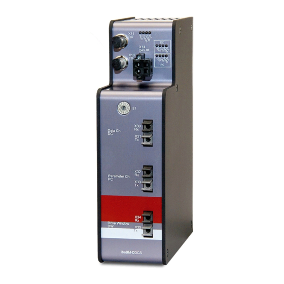
Manual Device layout Front view Operating status display Status LED data set query Status LED parameter query Plug for power supply X30 Rx (Link0 = Data set channel, CH0) X31 Tx (Link0 = Rx mirror, do not connect) X32 Rx (Link1 = Parameter channel, CH3) -
Page 14: Status Leds Data Set Query (2)
Status LEDs parameter query (3) Status Description DW (white) Connection for DriveWindow released Connection for ibaBM-DDCS released Link (yellow) blinking Blinks when a message is received (steadily lit when several messages are being received) Resp (white) on Data requested, all data are arriving... -
Page 15: X32 Rx (7) And X33 Tx (8)
Connection to the loopthrough of a computer with DriveWindow 7.5.8 Rotary switch S1 (11) Up to 15 ibaBM-DDCS devices can be interconnected in a ring topology. The devices are addressed via the rotary switch S1. Device numbers in the Rotary switch position... -
Page 16: Ibabm-Ddcs In Abb Environment
2 options for capturing and recording measured signals: 1. Logging of the signals in the data set channel (CH0 connection of the drives). Simplex fiber optic connection between ibaBM-DDCS X30 and an arbitrary channel of the NDBU-95 (NDBU operation mode: “REGEN”). The X31 output must not be connected to the NDBU-95. -
Page 17: Cascading Ibabm-Ddcs Devices
Manual Cascading ibaBM-DDCS devices Up to 15 devices supporting the ibaNet protocol 32Mbit Flex can be connected to each I/O link of an ibaFOB-D card in a fiber optic ring topology (e. g. ibaPADU-S-IT, ibaBM-eCAT). The rotary switch S1 has to be set to a unique device number at each device. -
Page 18: Data Set Channel
Manual ibaBM-DDCS Data set channel 8.3.1 Data sets The ABB control uses “data sets” to exchange information with the drives (CH0). Every data set consists of three 16-bit Integer values (indeces). A data set number and the data set index provide a given measurement or status value with ABB. -
Page 19: Star Topology With Ndbu Mode Regen
8 drives can be connected to each NDBU-95. Up to 16 NDBU-95 devices can be cascaded. The device ibaBM-DDCS must be connected via a unidirectional FO cable to that NDBU- 95, which is next to the controller. This NDBU-95 must be operated in REGEN mode, then the device can read all telegrams, including the response telegrams sent from the drives. - Page 20 Manual ibaBM-DDCS Important note When acquiring data sets in a star topology, ensure that the connected drives are set to “Star” topology. In DriveWindow, the parameter “CH0 HW CONNECTION” in the parameter set “DDCS Control” of each drive has to be checked and set to “STAR”.
-
Page 21: Star Topology With Ndbu Mode Ddcs/Drive Bus
8 drives can be connected to each NDBU-95. Up to 16 NDBU-95 devices can be cascaded. The device ibaBM-DDCS is coupled into the FO connection between NDBU-95 (MSTR.TX) and the controller (DDCS.RX). ibaBM-DDCS can read all telegrams sent from the drives to the controller. In order to read the output telegrams from the controller, a „bridge“... - Page 22 (decimal 124) DDCS/DRIVEBUS 4 MBIT/s AC800 M + CI858 Figure 6: ibaBM-DDCS connection (data sets) to NDBU-95, DDCS/DRIVE BUS mode Important note When acquiring data sets in a star topology, ensure that the connected drives are set to “Star” topology.
-
Page 23: Ring Topology
(CH0) takes the data which are addressed to it from the data stream and sends the reply data to the next drive. The last drive sends back the data to the controller. The ibaBM-DDCS device is coupled into the ring between the last drive and the controller. - Page 24 Manual ibaBM-DDCS Important note When acquiring data sets in a ring topology, ensure that the connected drives are set to “Ring” mode. In DriveWindow, the parameter “CH0 HW CONNECTION” in the parameter set “DDCS Control” of each drive has to be checked and set to “RING”.
-
Page 25: Parameter Channel
DDCS acts here as master and reads the current parameter values of the drives. ibaBM-DDCS is directly connected to the CH3 port of a drive or to the master port of the NDBU-95, which is connected to the drives (CH3). -
Page 26: Star Topology
Analog parameters in other formats, e. g. DINT, are misrepresented in ibaPDA. When there is only one drive, ibaBM-DDCS can be connected directly to the CH3 port (service channel) of the drive. When there are several drives, the communication can be established using a NDBU-95 in star or ring topology. - Page 27 When NDBU-95 units are cascaded, each unit must have a unique address between 76 and 124 – Units with higher addresses must be closer to the ibaBM-DDCS within the cascade – Use only even-numbered addresses Operating mode selection (X13): ...
-
Page 28: Ring Topology
Manual ibaBM-DDCS ibaBM-DDCS connection to NDBU-95 (parameter channel) Figure 11: ibaBM-DDCS connection (parameter) to NDBU-95 8.4.3 Ring topology A ring topology may often be found in older plants. The telegrams are sent from one drive to the next one via a FO ring. Every drive takes the data which are addressed to it from the data stream and sends the reply data to the next drive. -
Page 29: Connection Of A Computer With Drivewindow
Connection of a computer with DriveWindow ibaBM-DDCS offers a third fiber optic connection for connecting an external computer with DriveWindow software. The communication between the DriveWindow computer and the drives is looped through ibaBM-DDCS, there is no active data exchange with ibaBM-DDCS. Important note... -
Page 30: Time Response
The data acquisition cycle depends on the following parameters: Timebase of the ibaBM-DDCS interface in ibaPDA: Can be set in the ibaPDA I/O Manager under “ibaBM-DDCS - General - Time base”. Default value: ibaPDA acquisition timebase (I/O Manager – General). - Page 31 Manual Example: 8 analog parameter values are captured in total: 2 values which are set to “Fast” and 6 slow values. The 2 fast values and 1 slow value are sent with each cycle, in total 3 values. Hence, one cycle takes 6 ms.
-
Page 32: Configuration In Ibapda
Configuration in the I/O Manager Find the appropriate link of the FOB-D card to which the ibaBM-DDCS is connected in the I/O Manager. Click on the link with the right mouse button, which opens a submenu. Select “Add module”. Another submenu with all available devices will be displayed. -
Page 33: Ibabm-Ddcs - General Tab
Manual Now click on the link ibaBM-DDCS with the right mouse button and you can add the modules “Data set”, “Parameter” and “Diagnose”. Beginning with ibaPDA version 6.35, there is also the module type “Data set telegram counters” available. - Page 34 Enabled True: ibaBM-DDCS module is processed by ibaPDA False: ibaBM-DDCS module and all submodules are not processed Name Name of the module Use name as prefix If TRUE is selected, the module name is placed in front of the signal name as prefix.
-
Page 35: Ibabm-Ddcs - Diagnostics Tab
Write firmware With this link, you can update the firmware. Select the update file „bmddcs_vxxx.iba“ in the browser window and start the update with <OK>. The procedure takes several minutes and must not be interrupted. Reset to factory defaults Please note that configurations stored in the device are deleted after a reset. - Page 36 Manual ibaBM-DDCS Locked True: No changes possible. Only authorized users can unlock modules. False: Any user can make changes Enabled True: Data acquisition is enabled for this module False: Data acquisition is not enabled for this module Name Name of the module ...
- Page 37 Manual Figure 18: Data set browser Depending on whether the selected type is analog or digital, the signal will appear on the Analog or Digital tab. Node number (slave), data set number and index are entered automatically. Figure 19: Overview of the data set signals Complete control words, status words and fault words can be captured as analog value and itemized by 16 bit-decoders in ibaPDA.
-
Page 38: Module Type „Parameter
Manual ibaBM-DDCS 9.1.4 Module type „Parameter“ Here you can see the basic settings for the module and select the parameter signals. Figure 20: Parameter – General tab Basic settings Module type Display of the module type, cannot be modified ... - Page 39 Manual Advanced Enable default values True: In the event of a timeout, the last transmitted value will be overwritten by the default value. The default value can be preset in the Analog and Digital tabs. False: In the event of a timeout, the last transmitted value will remain.
-
Page 40: Module Type „Diagnose
Manual ibaBM-DDCS Figure 22: Overview of parameter signals A fast sampling rate is enabled by default in the column “Fast”. For signal values which change slowly, this setting can be manually disabled in order to reduce the load. Complete control words, status words and fault words can be captured as analog value and itemized by 32 bit-decoders in ibaPDA. - Page 41 Manual Name Name of the module Module no. Logical number of the module Timebase Acquisition timebase used for this module Use name as prefix If TRUE is selected, the module name is placed in front of the signal name as prefix.
-
Page 42: Module Type "Data Set Telegram Counters
Analog and Digital tabs. For an easier configuration, pre-configured diagnose modules for the most important diagnostic data were available on the DVD “iba Software & Manuals”, which is included in delivery. The modules could be imported in the I/O Manager: - Module 290: diagnostic counter for data set telegrams drive 1 –... -
Page 43: Display Of The Measured Values
9.1.7 Display of the measured values The current measurements of analog and digital signals and diagnostic values will be displayed on the Analog and Digital tab of the ibaBM-DDCS module. Figure 28: Actual values of the analog signals Issue 1.11... - Page 44 Manual ibaBM-DDCS Figure 29: Actual values of the digital signals All selected signals will be displayed in the ibaPDA signal tree. You can capture and record the measurements as usual. Figure 30: Measurements in ibaPDA Issue 1.11...
-
Page 45: Technical Data
Manual Technical data 10.1 Main data Short description Name ibaBM-DDCS Description Bus monitor for DDCS drive bus Order number 13.120710 DDCS interface Number 3 for one DDCS drive bus Design 2 HBFR Versatile Link connector (1 mm POF) for RX and... - Page 46 (incl. packaging and documentation) Supplier's Declaration of Conformity 47 CFR § 2.1077 Compliance Information Unique Identifier: 13.120710 ibaBM-DDCS Responsible Party - U.S. Contact Information iba America, LLC 370 Winkler Drive, Suite C Alpharetta, Georgia 30004 (770) 886-2318-102 www.iba-america.com FCC Compliance Statement This device complies with Part 15 of the FCC Rules.
-
Page 47: Dimension Sheet
Manual 10.2 Dimension sheet (Dimensions in mm) Figure 31: Dimension sheet ibaBM-DDCS (Dimensions in mm) Figure 32: Dimension sheet ibaBM-DDCS with cables Issue 1.11... -
Page 48: Support And Contact
Mailing address iba AG Postbox 1828 D-90708 Fuerth Germany Delivery address iba AG Gebhardtstrasse 10 D-90762 Fuerth Germany Regional and Worldwide For contact data of your regional iba office or representative please refer to our web site www.iba-ag.com. Issue 1.11...
Need help?
Do you have a question about the ibaBM-DDCS and is the answer not in the manual?
Questions and answers