Table of Contents
Advertisement
It is important to read the following instructions carefully before using this device
properly and safely. The manufacturer cannot be held responsible for the results of using
this device for any purposes other than described in these operating instructions.
If the use of this device may have caused or contributed to an undesirable event such as
death or serious injury to the user, the manufacturer AND the competent authority of the
Member State MUST be notified immediately!
EN109-1498751-47 IFU
January 16, 2020
4-SERIES
Page 1 of 72
Instructions for use
EN109-1498751-47 IFU
Advertisement
Table of Contents

Related Manuals for Enraf Nonius 4 Series


Summary of Contents for Enraf Nonius 4 Series
- Page 1 4-SERIES It is important to read the following instructions carefully before using this device properly and safely. The manufacturer cannot be held responsible for the results of using this device for any purposes other than described in these operating instructions. If the use of this device may have caused or contributed to an undesirable event such as death or serious injury to the user, the manufacturer AND the competent authority of the Member State MUST be notified immediately!
-
Page 2: Table Of Contents
Table of contents Introduction ..............................3 Symbols ................................5 Device components ............................7 Package contents ............................10 Installation ..............................13 Intended use and intended user ......................15 Indications ..............................16 Contraindications ............................17 Precautionary instructions ........................20 10 General instructions ............................ 21 11 Operation ................................ -
Page 3: Introduction
1 Introduction Foreword Welcome to the growing family of new 4-series owners. This product is designed and manufactured by Enraf-Nonius B.V. and is delivered to you with confidence. It was produced using the latest techniques and strict quality control. This manual has been written for the owners and operators of the 4-series. It contains general instructions on operation, precautionary practices, maintenance and parts information. - Page 4 The device is placed beneath the Endomed 482 or Sonopuls 492, from which its power is derived and through which it is also operated. Page 4 of 72 EN109-1498751-47 IFU...
-
Page 5: Symbols
2 Symbols Symbol used Description Follow the instructions in the Instructions for Use. It is important that you read, understand and observe the precautionary and operating instructions General Prohibition Sign. Prohibition is used to mean “You MUST NOT” Warning or Caution: Indicates a hazardous situation which, if not avoided, could result in: Death or serious injury to the patient (or) b. - Page 6 Serial Number Indicates the serial number so that a specific medical device can be identified. CE Mark along with number indicates conformity with European Council of directive concerning Medical Devices and this device is under the direct supervision of the Notified Body. Connection electrode cable electrotherapy Connections vacuum cables electrotherapy Remote control connection...
-
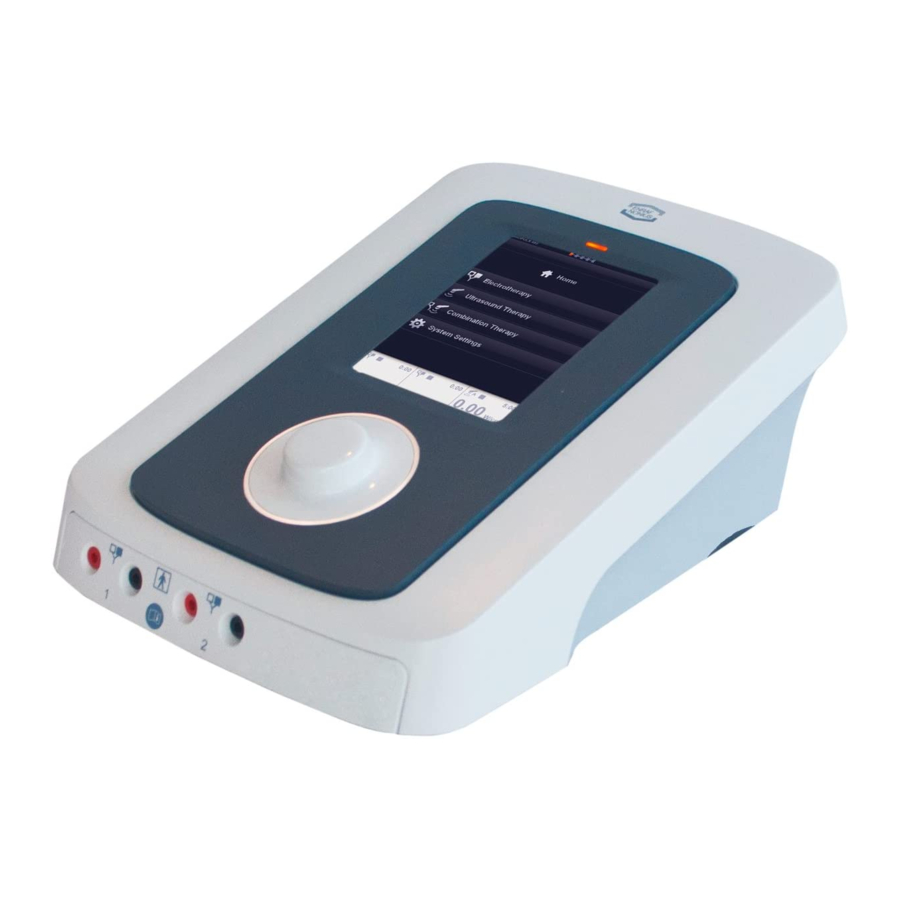
Page 7: Device Components
3 Device components Parts of the device Parts description Numbered Description Purpose Part Power line switch Device disconnected from mains supply Device connected to mains supply Connector for mains cable Connect supplied mains cable here to power the device. Type number/warning label Provides information on the apparatus, such as type and serial number, as well as connection data such mains... - Page 8 Numbered Description Purpose Part Do not connect externally powered USB devices or other information technology equipment as this can adversely affect the safety of the patient. The supply current of this connection is limited to 100 mA. Do not connect USB mass storage devices such as USB powered hard disks, as this might result in data loss.
- Page 9 Numbered Description Purpose Part and must therefore be avoided. Connections Vacuum Cables Connection point for the Vacuum Patient leads for [12] Electrotherapy channel 1 Channel 1. Connections Vacuum Cables Connection point for the Vacuum Patient leads for [13] Electrotherapy channel 2 Channel 2.
-
Page 10: Package Contents
4 Package contents Device The package contents depend on the device model ordered. The following models are available: Part Number Description 1498.901 Sonopuls 490 with large ultrasound treatment head 1498.902 Sonopuls 490 with small ultrasound treatment head 1498.903 Sonopuls 490 with large and small ultrasound treatment head 1498.911 Sonopuls 492 with large ultrasound treatment head 1498.912... - Page 11 Part Number Description 2 x 3444.211 Patient cable 2-core & 2 mm male plugs - black, with coloured clips Standard accessories vacuum Part Number Description 3444.505 Sponges Ø 65 mm, set of 4 (for vacuum electrodes Ø 60 mm) 2 x 3444.503 Vacuum electrodes Ø...
- Page 12 Part Number Description 3444.023 Strap 250x5 cm Point electrodes Part Number Description 3444.180 Point Electrode (pen model), 5 mm Ø, 2 mm female, incl 10 conductive rubber caps Adapters Part Number Description 2523.524 Adapter plug, 2 mm female, 4 mm male, red 2523.523 Adapter plug, 2 mm female, 4 mm male, black Patient cable...
-
Page 13: Installation
5 Installation Inspection In case of damage from transport is noticed, contact your local distributor. DO NOT USE the device! Immediately upon unpacking the device, perform the following steps: Verify the delivery documents to make sure that the delivery is complete. •... - Page 14 Remove the mains cable from the power line connector [1]. • Place the 4-series device upside down and on a soft surface. • Remove the two screws from the battery cover using the supplied screwdriver. • Slide and lift the battery cover. •...
-
Page 15: Intended Use And Intended User
6 Intended use and intended user Ultrasound therapy Ultrasound is a mechanical energy consisting of high-frequency vibrations applied by means of an ultrasound applicator. These vibrations pass through the tissue of the body and are gradually absorbed and transformed into heat. The resulting temperature increase triggers biological changes to occur in the tissue for the relief of pain, relaxation of muscle spasms and reduction of joint contractures. -
Page 16: Indications
7 Indications The 4-series can be used for the below mentioned symptoms or medical conditions. Electrotherapy Pain Management Symptomatic relief of chronic, intractable pain. Management of pain associated with post- • traumatic or postoperative conditions. Muscle Stimulation Relaxation of muscle spasms •... -
Page 17: Contraindications
8 Contraindications The 4-series MUST NOT be used for the below mentioned symptoms or medical conditions. Electrotherapy Pain management This device should not be used for symptomatic pain relief unless etiology is established or unless • a pain syndrome has been diagnosed. This device should not be used on patients with demand-type cardiac pacemakers. - Page 18 Combination therapy The combined Contra-indications of ultrasound therapy and electrotherapy apply. Precautions and warnings Ultrasound therapy Precaution should be taken when using therapeutic ultrasound on patients with hemorrhagic diathesis. Ultrasound treatment presents a potential safety hazard in patients whose pain response has been decreased because of disease, previous surgery, ionizing radiation therapy, chemotherapy, general or regional anaesthesia.
- Page 19 conductive medium, or alternate electrode placement. See also chapter 9 for general warnings and precautions. Combination therapy Combination therapy is only allowed with a single ultrasound head connected. Relevant hazards Ultrasound therapy Use of ultrasound in treating areas above the shoulders may pose relevant hazards. While it is •...
-
Page 20: Precautionary Instructions
9 Precautionary instructions Warning! Federal law (USA only) restricts this device to sale by, or on the order of, a physician or licensed practitioner. This device should be used only under the continued supervision of a physician or licensed practitioner. Keep yourself informed of the contra-indications. -
Page 21: General Instructions
10 General instructions Ultrasound therapy During treatment, the patient may not feel unpleasant sensations amounting to pain. A mild sensation of excitation is permissible. If, as result of treatment, headache, vertigo, fatigue and/or other (autonomic nervous) reactions develop, subsequent treatment should be given at a lower intensity. With continuous and pulsed ultrasound at high intensity a sensation of heat may be felt. - Page 22 Electrotherapy During treatment, the patient may not feel unpleasant sensations amounting to pain. A mild sensation of excitation is permissible. If, as result of treatment, headache, vertigo, fatigue and/or other (autonomic nervous) reactions develop, subsequent treatment should be given at a lower intensity. Before treatment Please make sure you have read and understood the content of this manual before you start treatment.
-
Page 23: Operation
11 Operation Set up Turn on the apparatus Switch the unit ON via the push button [4]. The unit starts by executing the self-test. At the end of the self-test a beep sound can be heard and the unit enters the Home menu and is ready for use. - Page 24 navigate to the next screen. You can navigate back to the previous screen by touching the back arrow at the top of the screen. Anywhere in the navigation, you can jump back to the Home menu, by touching the home button. Navigation bar The following buttons can appear in the navigation bar [D].
- Page 25 Unit of Output value: µA, mA, V, W, W/cm Adjusting current amplitude To adjust the output current, touch the tab of the selected channel. Its colour will change to orange, after which the current amplitude can be set with the central controller [7]. The current amplitude can only be adjusted when the clock has been set.
- Page 26 Ramp down time, expressed in seconds, defines the time in a surge program during which the current is decreased from the adjusted level to 0. See Figure 30 for details. The ramp down time can be adjusted in increments of 0.1 second. Interval time, expressed in s, defines the time in a surge program during which the current is kept at 0.
- Page 27 Use the central controller to scroll through the list and select the clinical protocol by touching the button. The channel selection screen appears. For therapy information touch the info button on the left side of the protocol and the therapy info will appear. Therapy information Use the central controller to scroll through the pages, in most cases the first page is text followed by one or more illustrations.
- Page 28 Parameter screen (therapy screen) In this screen, the user can adjust the intensity or change the parameter by touching the button and changing the value with the central controller. If there is a vacuum unit available the user can set the vacuum settings direct from the menu.
- Page 29 Select from the list a current waveform Scroll to the next page with the central controller [7] or select the current waveform by touching the button. Note: some of these selections are groups and in the next screen another list appears from which the current waveform can be selected.
- Page 30 Treatment time adjustment Touch the timer button, the colour changes into white and adjust the treatment time with the central controller [7]. Repeat this for all other parameters. Start the therapy by adjusting the intensity with the central controller [7]. To pause the treatment, touch the pause button in the •...
- Page 31 Ultrasound Therapy “Clinical Protocols” The Ultrasound Therapy menu gives access to functions Clinical Protocols • Favorites • Manual Operation • Select Clinical Protocols by touching the button. The next screen appears. Use the central controller to scroll through the list and select the clinical protocol by touching the button.
- Page 32 Touch the accept button in the navigation bar. ✓ The parameter screen appears. Channel Selection Here you can select the channels for Ultrasound. When channel A is selected, channel B is still available for another therapy. (Functionality may be limited if the dual channel mode is not activated.) The count-down starts when there is sufficient contact between the applicator and the treatment surface.
- Page 33 Combination Therapy This therapy combines ultrasound and electrotherapy. The Home menu gives access to all functions of the unit. Select in the Home menu combination therapy by touching the button “Combination Therapy”. The next screen appears. The Combination menu gives access to functions Clinical Protocols •...
- Page 34 Channel Selection Here you can select the channels for Ultrasound. Note: A notification may appear if there are more than 1 Ultrasound treatment head connected. Follow the instructions of the notification. Adjust the current parameters and treatment time Touch the parameter button and adjust with the central •...
- Page 35 Select the ultrasound button to adjust the ultrasound • parameters. Touch the electrotherapy button to return to the previous • electrotherapy screen. Touch the ultrasound read-out and adjust the intensity • with the central controller [7]. Touch the current read-out channel 2 to adjust the •...
- Page 36 Continuous – Pulsed mode Touch the – button and select the desired massage • rhythm using the central controller [7]. You can choose between Continuous, Pulsed mode 1 s and Pulsed mode 2 s. Storing Favorites When a treatment screen is completely set as required, its settings can be stored in a Favorite for later use: As long as the treatment has not been started, a Store •...
- Page 37 Programming a Sequential Protocol A sequential protocol consists of a series of treatment steps that are executed in a sequence until the end of the protocol is reached. Select Programming in the electrotherapy menu. • When a treatment screen is completely set as required, •...
- Page 38 In this screen, you can personalize the unit. Several settings can be changed or adjusted. Touch the Back arrow in the navigation bar to return to the Home menu. Language, touch the language button and select the • desired language using the central controller [7]. Touch the language button again or touch another button to confirm.
-
Page 39: Application Information
12 Application information Before starting the treatment please make sure: You have read and understood the content of this manual. You strictly follow the WARNINGS and CAUTIONS mentioned under precautionary instructions. Check the patient for any possible contra-indications. Connection of accessories other than the ones specified by the manufacturer can adversely affect the safety of the patient and correct functioning of the equipment, and is therefore not permitted. - Page 40 Vacuum electrodes There is a choice of large and small electrodes. The areas of the electrodes correspond to those of the 4 x 6 cm and 6 x 8 cm flexible rubber electrodes. The vacuum electrodes are sufficiently flexible to ensure optimum contact with the skin, but rigid enough to prevent any changes in the contour of the part being treated, allowing full advantage to be taken of the massage effect of the pulsed vacuum.
- Page 41 See paragraph Vacuum electrodes for the application of the vacuum electrodes. • When you use only one vacuum channel, close the other channel with one of the vacuum cables • not in use. Electrolytic effects Electrolysis occurs under the electrodes when current types with a DC component are applied. Because the largest concentration of electrolytic by-products caused by ion migration occur under the electrodes, we recommend the use of the supplied sponges to keep the effects to a minimum.
-
Page 42: Description - Current Waveforms And Ultrasound Parameters
13 Description – Current waveforms and Ultrasound parameters 4 pole interferential currents With the interferential current type a medium frequency carrier frequency is used to pass the low frequency stimulation (beat) frequency through the skin. The relatively low resistance of the skin to the carrier frequency contributes to the patient comfort that is often associated with this current type. - Page 43 Dipole vector manual With the dipole vector technique, the currents from the two electrode pairs are vectorially summed in the tissue. The effect is that stimulation only occurs into the direction of the resulting vector, which can be adjusted over a range of 360º. Amplitude modulation occurs in the equipment and the modulation depth is 100%.
- Page 44 A variation to the standard biphasic asymmetrical pulsed current is the alternating one, in which the successive pulse phases alternate with respect to the baseline (figure 7). This waveform is also fully balanced. To prevent accommodation to stimulation or to improve patient tolerance, the pulse frequency can be varied through frequency modulation.
- Page 45 Surge Program can be used to adjust repeated sequences of contraction and rest periods. • Burst symmetrical The burst biphasic symmetrical pulsed current is a variation to its non-burst counterpart, in which the continuous train of pulses is interrupted by pulse pauses. See Figure 12 for details. A burst frequency can be set for treating chronic pains, where the use of continuous stimulation with a low pulse frequency would be too painful.
- Page 46 A specific feature of this type of muscle stimulation is that the alternating current is interrupted 50 times per second. This results in a pulse train, comparable to the ‘burst’ in TENS. The total duration of the pulse train is 20 ms, giving a phase duration/phase interval ratio of 1:1. Kots uses a Burst frequency of 50 Hz, approximately in the middle of the frequency spectrum used to produce tetanic contraction (40-80 Hz).
- Page 47 Frequency Modulation, expressed in %, defines a variable frequency range that is subtracted • from the Pulse frequency i.e. when the Pulse frequency is set to 80 Hz and the Frequency modulation is set to 50%, the final frequency will vary from 40 – 80 Hz. Modulation Program defines the time and sequence in which the frequency will sweep through •...
- Page 48 Parameters: Surge Program can be used to adjust repeated sequences of contraction and rest periods. Surge • programs are only available with MF and DF. Galvanic current Continuous galvanic current The Direct Galvanic Current is a monophasic current that produces electrolysis by-products. These by-products can result in etching beneath the electrodes.
- Page 49 Träbert, 2 – 5 Current Faradic currents are monophasic currents that produce electrolysis by-products. These by- products can result in etching beneath the electrodes. Always use properly moistened sponge / electrode combinations to absorb these by-products during treatment. The 2-5 or ‘Ultra-Reiz’ current was introduced by Träbert (*). It is often used to treat headaches and neck pain.
- Page 50 Biphasic pulsed current TENS Asymmetrical IGURE Phase duration Pulse frequency Asymmetrical alternating IGURE Phase duration Pulse frequency Burst asymmetrical IGURE Burst frequency Burst asymmetrical alternating IGURE Burst frequency Symmetrical IGURE ...
- Page 51 Burst symmetrical IGURE Burst frequency Faradic Current Träbert, 2 – 5 current IGURE Phase duration: 2 ms Phase interval: 5 ms Rectangular pulsed current (ms) IGURE Phase duration Phase interval ...
- Page 52 Triangular pulsed current (ms) IGURE Phase duration Phase interval Triangular pulsed current (Hz) IGURE Phase duration Pulse frequency Galvanic current Galvanic interrupted IGURE Carrier frequency - 8 kHz fixed Duty cycle - 90 % fixed Galvanic continuous IGURE High voltage IGURE ...
- Page 53 Diadynamic current IGURE IGURE IGURE IGURE CPid IGURE Modulation program Modulation program 1/1 IGURE Pulse frequency Frequency modulation Page 53 of 72 EN109-1498751-47 IFU...
- Page 54 Modulation program 6/6 or 12/12 IGURE 6:6 or 12:12 Pulse frequency Frequency modulation Modulation program 1/30 IGURE 1:30 Pulse frequency Frequency modulation Surge program Surge program parameters IGURE Ramp up time Hold time Ramp down time Interval time Delay time ...
- Page 55 Current waveforms – Pain management For pain management, the following current waveforms are recommended. 4-Polar Interferential Currents • Biphasic Pulsed Currents (TENS) • Premodulated • Micro Current • High Voltage • Diadynamic Currents • Galvanic Current • Träbert, 2 – 5 Current •...
- Page 56 Stimulator output parameters Electrotherapy general Channels Output characteristics : Constant Current (CC) or Constant Voltage (CV), except for High Voltage (CV) and Microcurrent (CC). Current amplitude range : Depending on current waveform Current amplitude resolution : 0.2 mA Treatment timer : 0 –...
- Page 57 Pulse Frequency : 1 – 200 Hz, in steps of 1 Hz Frequency Modulation : 0 – 180 Hz, in steps of 1 Hz Modulation Program : 1/1, 6/6, 12/12, 1/30/1/30 s Surge Program : Yes Amplitude : 0 - 140 mA Asymmetrical Alternating Phase Duration : 10 –...
- Page 58 Burst / Pause : 1:1, 1:2, 1:3, 1:4, 1:5 Surge Program : Yes Amplitude : 0 – 100 mA High Voltage (Twin Pulse) Frequency : 1 – 200 Hz in steps of 1 Hz Frequency Modulation (spectrum) : 0 – 180 Hz in steps of 1 Hz, sum of Pulse frequency and Frequency Modulation cannot exceed 200 Hz Modulation Program : 1/1, 6/6, 12/12, 1/30/1/30 s...
- Page 59 Faradic Rectangular Pulsed Current (ms) Phase Duration : 0.02 – 1000 ms Phase Interval : 5 – 50 ms in steps of 5 ms, 50 – 100 in steps of 10 ms, 100 – 1000 ms in steps of 100 ms, 1 – 5 seconds in steps of 1 second Surge Program : Yes Polarity...
- Page 60 Ultrasound parameters Ultrasound Frequency, expressed in MHz, is the frequency of the ultrasound waves. The ultrasound frequency determines the penetration depth, which has the largest value at 1 MHz. The ultrasound frequency can be set at 1 MHz or 3 MHz. Duty Cycle, expressed in %, defines the ratio of the pulse duration to the pulse repetition time.
- Page 61 Amplitude Duty cycle Pulse RTPA Amplitude Duty cycle Pulse RTPA modulation duration modulation duration 16Hz 3.1ms 48Hz 10.4ms 16Hz 6.3ms 48Hz 16.7ms 1.25 16Hz 12.5ms 48Hz 100%* 20.8ms 16Hz 20.6ms 100Hz 0.5ms 16Hz 31.3ms 100Hz 16Hz 50ms 1.25 100Hz 16Hz 100%* 62.5ms 100Hz...
- Page 62 Beam type: 1 MHz : Collimating 3 MHz : Collimating BNR (Beam Non-uniformity Ratio) : 6:1 maximum Side radiation : 10 mW/cm² maximum 0.8 cm² Applicator Ultrasound frequency: 1 MHz : 0.98 MHz ± 5 % 3 MHz : 3.1 MHz ± 5 % ERA (Effective Radiation Area): IEC 60601-2-5: 2000 : 0.6 cm...
-
Page 63: Maintenance And Troubleshooting
14 Maintenance and troubleshooting Cleaning and disinfection Before performing any user maintenance, switch off the device and disconnect the plug from the mains supply. Do not spray the cleaning agent directly on the glass panel. Do not use cleaning agents that contain strong alkalis, lye, acid, detergents with fluoride or detergents with ammonia. - Page 64 Cleaning the Detach the vacuum cups from the vacuum cables. • water reservoir Place a container filled with a cleaning liquid (*) below the system. • and hoses Place the peripheral ends of the cables in the container. • Go to System Settings and select Tank Cleaning. •...
- Page 65 Vacuum leak There probably is a leak in the vacuum system. This error is usually preceded by a continuously running pump trying to reach the set vacuum. To protect the system, the pump is automatically stopped after a certain amount of time. Inspect the vacuum cables and electrodes, set the vacuum back to zero and try again.
- Page 66 Intended use of dual channel ultrasound therapy is for one patient only This notification is shown when activating the Dual Channel functionality of the device. The purpose is to remind the operator that the intended us of Dual Channel Ultrasound is for a single patient only. Favorite is in use on a channel.
- Page 67 Technical maintenance Electrical safety of the device relies on a properly earthed electrical connection via the power cord. It is therefore necessary to have this connection checked annually. To ensure continued compliance with the 21 CFR 1050.10 standard, this unit should be adjusted and safety tested once each year.
-
Page 68: Specifications
15 Specifications Technical data Mains voltage: 100 - 240 Volt Frequency: 50/60 Hz Max. power input: 100 VA Patient leakage current: typically, 1 μA idem single fault condition: typically, 2 μA Main Unit Dimensions stand alone 24 x 32 x 12 cm (w x d x h) Dimensions on inclination foot 24 x 30.5 x 18.2 cm (w x d x h) Dimensions on Vacotron... - Page 69 Environmental conditions Environmental conditions for transport and storage Environmental temperature: –20° to +70° C Relative humidity: 10 to 90% (non-condensing) Atmospheric pressure: 500 to 1060 hPa Environmental conditions normal use Environmental temperature: 10° to 40° C Relative humidity: 10 to 90 % (non-condensing) Atmospheric pressure: 500 to 1060 hPa EMC details...
-
Page 70: Contact
16 Contact For assistance, please visit our website http://www.enraf-nonius.com The latest version (in electronic or printed format) of this Instructions for Use can be obtained free of charge from our website www.enraf-nonius.com or by contacting distributor or by calling the telephone number: +31-(0)10-2030600. - Page 71 Page 71 of 72 EN109-1498751-47 IFU...
- Page 72 Copyright: Enraf-Nonius B.V. Vareseweg 127 | 3047 AT | Rotterdam | The Netherlands Tel: +31 (0)10-20 30 600 | info@enraf-nonius.nl EN109-1498751-47...
Need help?
Do you have a question about the 4 Series and is the answer not in the manual?
Questions and answers