Advertisement
GENERAL DESCRIPTION
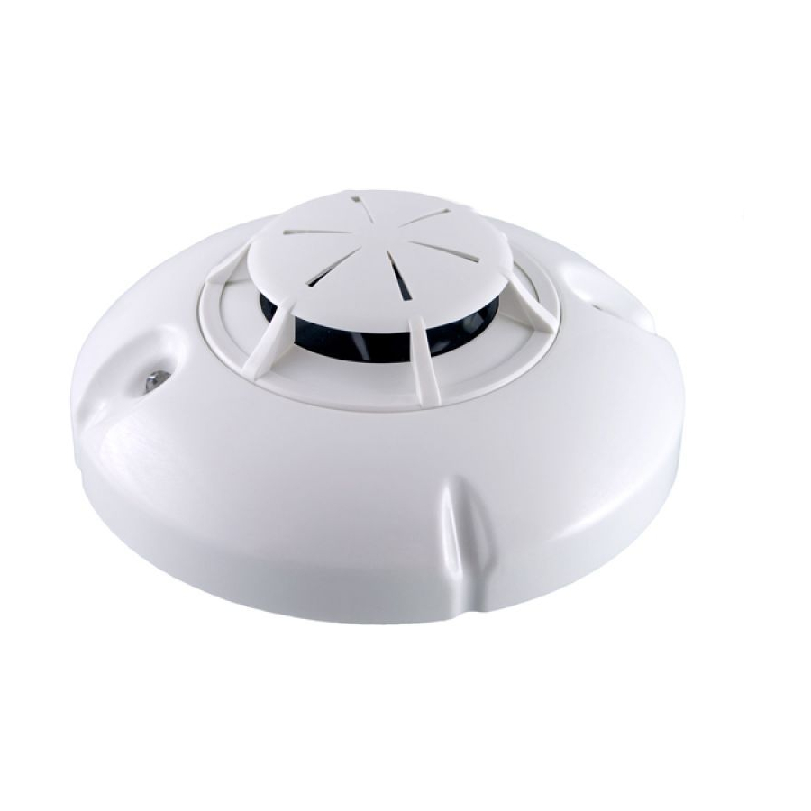
Conventional line-monitoring module 7201 is designed to connect up to 32 conventional fire detectors to an
addressable fire alarm control system type IFS7000 and to monitor the protected area through a built-in rate of
rise heat detector.
Fire control panel IFS7002 is able to exchange information with the module through a specialized
communication protocol UniTALK and supplies power to the module via its signal loop. The status of the signal
loop is monitored through a short circuit isolator built-in the conventional line monitoring module.
The unit comprises a printed circuit board and a heat chamber (fig.1 pos.4 ) placed in a plastic body (fig.1 pos.5).
Terminals for connection to the signal loop –IN/OUT, +IN (fig.1 pos.8) and for conventional detectors line RI/KL-,
KL+ (fig.1pos.7) are provided on the base type 7100A (fig.1pos.1). The module is completed with a terminating
component EOL-1 having a red R and a black B leads (fig.1 pos.9) that shall terminate the conventional fire alarm
line.
The red and yellow LEDs situated on the body of the module (fig. 1 pos.3) provide information for the following:
Duty mode - both LEDs flash every 16 seconds;
Built-in detector in Fire condition – the red LED illuminates continuously; the yellow LED is extinguished;
Fire detector in the conventional line in Fire condition – the red LED flashes repeatedly every 1 sec., the
yellow LED is extinguished;
Activated short circuit isolator for the signal loop – the red LED is extinguished; the yellow LED flashes
repeatedly every 1 sec;
Removed fire detector in the conventional line - the red LED is extinguished; the yellow LED produces double
flashing light, repeatedly every 1 sec;
Short circuit or break in the conventional line - the red LED is extinguished; the yellow LED produces
continuous light.
TECHNICAL DATA
Supply voltage of the signal loop
Current of the signal loop in Duty mode
Current of the signal loop in Fire condition in the built-in detector
Current of the signal loop in Fire condition in a detector integrated
in the conventional fire alarm line
Voltage of the conventional fire alarm line
Current of the conventional line when registered:
- Break in a line
- Duty mode
- Fire condition
- Short circuit
Area protected by the built-in rate of rise heat detector
Maximum cross-section of the connecting wires
Type of the connecting wires
- signal loop
- conventional fire alarm line
Degree of protection
Operational temperature range
Relative humidity resistance
Dimensions (base incl.)
Weight
INSTALLATION
Conventional line monitoring module type FD7201 shall be mounted onto base type 7100А. To install the
module and its base please follow the sequence:
1. Fix the base on the ceiling of the protected premises using appropriate fixings.
2.Complete the wiring as shown on fig. 2 and in accordance with the construction projects of the site. Terminate
the conventional fire alarm line using the provided terminating component.
Note: We recommend you to install diodes on the bases of all conventional fire detectors. Otherwise in case of
a removed conventional detector the module will indicate break in the conventional line.
3. Replace the conventional line-monitoring module on the base and rotate it in a clockwise direction to reach
the base's leading channels (Fig.1.1, position 2). Continue rotating in a clockwise direction to complete location
(Fig.3.1). The bench marks of the module and the base should fully coincide (Fig. 3.2).
4. To lock the module to the base separate the key from the base (Fig. 1.2, position 9) and keep it in a safe place,
cut the technological edge (Fig. 1.2, position 7) of the click (Fig. 1.2, position 8) and complete the instructions
described above.
5. To unlock the module insert the key into the slot, according to Fig.4, rotate the module anticlockwise until rest,
take the key out and continue rotating to release the module.
TESTING THE CONVENTIONAL LINE-MONITORING MODULE
Test the module with conventional detectors connected, and after connecting the module to fire control panel
type IFS7002 as a part of the site's fire alarm system.
1. Set the control panel to Duty mode. The conventional line-monitoring module shall enter Duty mode and shall
indicate the condition accordingly, as described above.
2. Set the built-in heat detector or set
condition. The module shall indicate the condition accordingly, as described above.
3. Send a reset command from the fire control panel IFS7002 to the conventional line-monitoring module. The
module shall restore the Duty Mode
SERVICE SCHEDULE
№
Task description
1.
Inspection for visible physical damage
2.
Satisfactory operation test in real conditions
3*
Check and clean dust contamination
4.
Check and clean base and head contacts and connections
* To complete task №3, remove the detector's upper part (Fig. 1, position 6). Clean using a small
brush. The upper part is removed by rotating it anticlockwise until rest.
WARRANTY
The warrant period is 36 months from the date of purchase. The manufacturer guarantees the normal
operation of the unit providing that the requirements set herein have been observed. The manufacturer does
not bear warranty liabilities for damages caused through accidental mechanical damage, misuse, adaptation
or modification after production. The manufacturer bears warranty liabilities for damages in the fire detector
caused through manufacturer's fault only.
Manufacturer: UniPOS Ltd., 114 Grenaderska Street, Pleven 5800, Bulgaria, http://www.unipos-bg.com
CONVENTIONAL LINE-MONITORING MODULE
Type FD7201
Instruction Manual 01-7201-11-05
twice
any detector connected to the module's conventional line, to Fire
(15-30)V DC
(4-8) mA
5 mA at 24 VDC
(8-50) mA
-
(15-30)V DC
(0-2 mA
(2-10) mA
(10-50) mА
higher than 50 mA
circle with diameter 10m
at h<8m
2
2,5 mm
two-wire, shielded
two-wire
IP 43
minus 10°С - plus 55°С
(93 ±3)% at 40°С
Ø100 mm, h 47mm
0,100 kg
Table 1
Periodicity
weekly
monthly
every 6 months
Annually
1293
Advertisement
Table of Contents

Related Manuals for UniPOS FD7201


Summary of Contents for UniPOS FD7201
- Page 1 0,100 kg INSTALLATION Conventional line monitoring module type FD7201 shall be mounted onto base type 7100А. To install the module and its base please follow the sequence: 1. Fix the base on the ceiling of the protected premises using appropriate fixings.
- Page 2 EOL-1 Fig.1 IFS7002 RI/KL RI/KL -IN/OUT EOL-1 -IN/OUT FD7201 FD80XX +OUT +OUT RI31/RI31S Fig.2 Fig.3.2 Fig.3.1 Fig.4 Manufacturer: UniPOS Ltd., 114 Grenaderska Street, Pleven 5800, Bulgaria, http://www.unipos-bg.com...
Need help?
Do you have a question about the FD7201 and is the answer not in the manual?
Questions and answers