Table of Contents
Advertisement
Quick Links
Advertisement
Table of Contents

Related Manuals for crosscontrol CCpilot V700


Summary of Contents for crosscontrol CCpilot V700
- Page 1 Revision: 1.0 2020-09-10 CCpilot V700 Technical Manual www.crosscontrol.com...
-
Page 2: Introduction
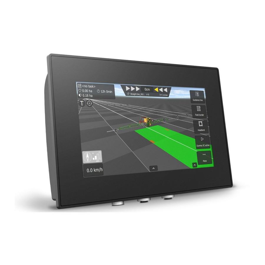
Technical Manual 2020-09-10 1. Introduction CCpilot V700 is a freely programmable display computer with 7” high brightness full-colour WVGA TFT with PCAP touch screen. The strong LED backlight in combination with the optically bonded PCAP, results in excellent sunlight readability. -
Page 3: Table Of Contents
CCpilot V700 Revision: 1.0 Technical Manual 2020-09-10 Contents 1. Introduction ..........................2 Revision history ..........................2 2. Product models ......................... 4 2.2. Document conventions ....................... 4 2.3. Identification ......................... 4 2.4. Environmental resistance ..................... 5 3. Product overview........................5 3.1. Front side view ........................5 3.2. -
Page 4: Product Models
Revision: 1.0 Technical Manual 2020-09-10 2. Product models This documentation is applicable for all CCpilot V700 models. These models are: • CCpilot V700 standard version of product. Part number C000152-04 • CCpilot V700 standard with Bluetooth module. Part number: C000152-01 CCpilot V700 custom version. -
Page 5: Environmental Resistance
Technical Manual 2020-09-10 2.4. Environmental resistance The CCpilot V700 product has been designed to manage tough environmental demands. Much effort has been put into designing and selecting system components to provide a reliable and robust device. Thorough testing has been performed in order to ensure compliance to a broad range of applicable regulatory requirements and to meet user demands of a ruggedized product for machinery control. -
Page 6: Connector Side View
4.1. Mounting CCpilot V700 supports two different mounting methods, a RAM mount or a panel mount. These two mounting methods are described separately below. For both fastening methods, use the appropriate 3 pc. M5 x 0.8 button head screw of type MRT (Torx) The recommended torque for the screws is 1.5-2.0 Nm. - Page 7 6 mm to avoid pulling out the threaded inserts from the unit. 4.1.1. RAM mount CCpilot V700 can be mounted using a RAM mount, i.e. RAM-202U, a round base 1.5” ball mount which allows adjustment of the display’s position and angle. Screw length should be 12mm.
- Page 8 CCpilot V700 Revision: 1.0 Technical Manual 2020-09-10 Figure 6: Mounting bracket The mounting bracket is designed for a panel thickness of 1.5 - 3.0 mm. Panel cut out dimensions are shown in the figure below. A drawing in DXF-format for precision cutting of panels is available upon request.
-
Page 9: Connecting To Power Supply
Technical Manual 2020-09-10 Ensure that CCpilot V700 is mounted to a smooth, flat surface. Fastening the unit to an uneven surface may stress the enclosure, damage the outer flange or possibly even flex the circuit board inside, leading to a premature failure. - Page 10 Device B Device C Figure 7: Schematic example for power supply installation of a CCpilot V700 device in a vehicle. The ignition switch (S2) can be shared by several devices (Device X, Y, …) By connecting the power supply according to the example above, the CCpilot V700 device will automatically start up when the key switch (S2) is closed and shut down when the switch is opened.
-
Page 11: Cable Installation
CCpilot V700 Revision: 1.0 Technical Manual 2020-09-10 running, the battery may be drained, resulting in inability to start up the vehicle. A main switch for disconnecting the device’s main supply is highly recommended in such situations. 4.3. Cable installation Cables shall be installed in such a way that they do not run any risk of being damaged, pinched or worn. -
Page 12: Handling And Maintenance
Always consider personal safety when installing and operating the product. For example, in vehicle installations, CrossControl does not recommend that the product is being actively operated by the driver when a risk of injury to people or damage to property is present. -
Page 13: Transportation
CCpilot V700 Revision: 1.0 Technical Manual 2020-09-10 4.6. Transportation When transporting the device it is recommended to use the original packaging. Make sure that protective caps are used on all non-mated connectors. The storage temperature interval [-40°C to +80°C] must be met. -
Page 14: Basic Operation
When the device enters operational state the status LED will stop flashing and be turned on. 5.2. Turning OFF and suspending There are several ways to turn off the CCpilot V700 device and also alternatives to enter suspend mode instead of completely shutting down the device. -
Page 15: Light Sensor
CCAux API. See the software guide for details. 5.3. Light sensor The CCpilot V700 contains a light sensor that can be used to automatically adjust the display brightness, depending on the ambient light conditions. As depicted in Figure 2, the light sensor is located in the lower right corner of the front surface. -
Page 16: Using The Touch Screen
5.5. Status notification The CCpilot V700 contains a status LED in the front used for notification while starting up, shutting down or in other operational states. The buzzer may also be used for user notifications. - Page 17 The error code in persistent storage can be read and cleared from a user application. Refer to Table 2: CCpilot V700 error codes for a complete listing of the error codes. The number of blinks is important information if the unit is sent in for service/repair.
-
Page 18: Interface Overview
For light sensor location, see Figure 2. Refer to the CCpilot V700 Software guide for details about accessing the light sensor data from user applications. 6.1.3. RGB status LED The CCpilot V700 contains a status LED in the front used for notification while starting up, shutting down or in other operational states. 6.2. Buzzer The CCpilot V700 has a built-in buzzer that can be used for audible notifications. -
Page 19: Usb
IT security threat. 6.5. USB The CCpilot V700 has one (1) USB port. This port supports an USB OTG interface, i.e. acting as both host and device. Using the port in USB device mode is only for OS updates through a connected PC with appropriate tool installed. -
Page 20: Connectors
CCpilot V700 Revision: 1.0 Technical Manual 2020-09-10 7. Connectors There are three M12 connectors, marked with 1, 2 and 3 accessible from the side of the device. Refer to 9 for an overview of the connectors. 7.1. M12 connectors, general Pay close attention to the coding;... -
Page 21: Ethernet M12 Pinout
CCpilot V700 Revision: 1.0 Technical Manual 2020-09-10 7.3. Ethernet M12 pinout Ethernet M12 Connector Matching plug: Male, 4-pin, D-coded with shield Signal Housing Shield Table 10: Ethernet M12 connector pinout 7.4. USB M12 connector pinout USB M12 Connector Matching plug: Male, 5-pin, A-coded with shield... -
Page 22: Specifications
CCpilot V700 Revision: 1.0 Technical Manual 2020-09-10 8. Specifications 8.1. Technical data Temperature specification Operating -30 to +70 °C Storage -40 to +80 °C Kernel Main Processor ® NXP™ i.MX8 DualXPlus: ARM 64-bit, 1200MHz, Cortex -A35 Co-processor ® STMicroelectronics STM32F071VB, Cortex... - Page 23 The buzzer is located on the back (connector side) of the device and the effective SPL varies dependent on the acoustic properties of the installation environment. Software Operating system CCLinux CCAux API, CCSettingsConsole. Refer to the CCpilot V700 Software Additional software Guide and Programmer’s guide for details. Display Size Diagonal size 7.0 inch widescreen...
-
Page 24: Environmental Specifications
Enclosure Ingress Protection IEC 60529:2014 IP65, IP66 and IP67 Any changes or modifications to the device not expressly approved by CrossControl could void the environmental classification, warranty, and user's authority to operate the equipment. 8.3. EMC specification The CCpilot V700 device has been tested for Electromagnetic Compatibility according to the following standards EN ISO 14982, EN ISO 13766-1 and EN ISO 13766-2. -
Page 25: Weight And Dimensions
201 x 135 (140) x 40 mm (W x H (H+connector) x D) Weight 0.62kg RAM-202U Mounting holes Spacing Dia 46 mm Thread dimension Thread depth 8.0 mm PBT + PC plastic, impact Enclosure material modified and flame retarted Figure 6: CCpilot V700 dimensions. www.crosscontrol.com... -
Page 26: Technical Support
Technical Manual 2020-09-10 Technical support Additional sources of information are available on the CrossControl support site: http://support.crosscontrol.com Contact your reseller or supplier for help with possible problems with your device. In order to get the best help, you should have your device in front of you and be prepared with the following information before you contact support. -
Page 27: Trademarks And Terms Of Use
CrossControl. CrossControl respects the intellectual property of others, and we ask our users to do the same. Where software based on CrossControl software or products is distributed, the software may only be distributed in accordance with the terms and conditions provided by the reproduced licensors.
Need help?
Do you have a question about the CCpilot V700 and is the answer not in the manual?
Questions and answers
May i know the ECCN for this item ( CrossControl : V700 Sandvik SW, CCL3 => C000100-584 )