
Related Manuals for AVProEdge AC-EX70-UHD-ARC


Summary of Contents for AVProEdge AC-EX70-UHD-ARC
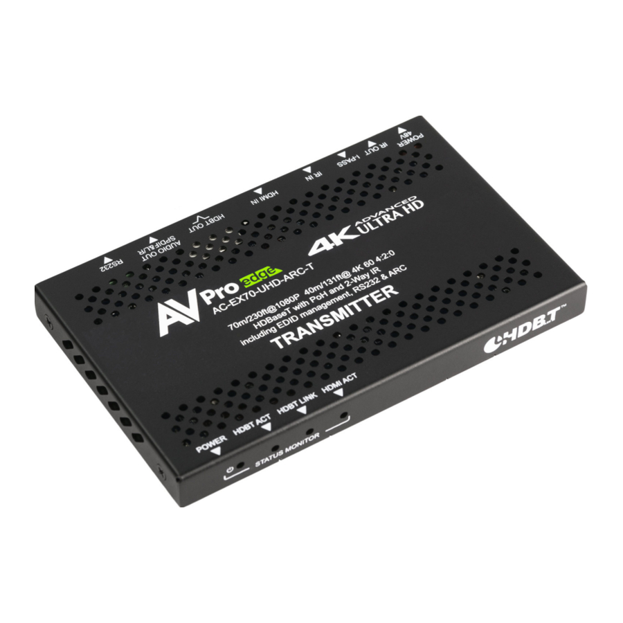
- Page 1 USER MANUAL Ultra Slim 4K HDMI via HDBaseT 70 Meter Extender with Bi-Directional Power and ARC support AC-EX70-UHD-ARC...
-
Page 2: Table Of Contents
Table of Contents I N T R O D U C T I O N � � � � � � � � � � � � � � � � � � � � � � � � � � � � � � � � � � � � � � � � � � � � � � � � � � � � � � � � � � � � � � � � � � � � � � � � � � � � � � � � � � � � � � � � � � � 3 F E A T U R E S �... -
Page 3: Introduction
Introduction The AC-EX70-UHD-ARC consists of a transmitter and receiver that connect via single CAT-6a/7 UTP/STP. Connecting an HDMI signal to the transmitter allows for sending HDMI signals up to 70 meters at 1080p and up to 40 meters at 4K60 4:2:0, 4K30 4:4:4. -
Page 4: Specifications
Specifications... -
Page 5: Troubleshooting Lights - Transmitter/Receiver
Troubleshooting Lights - Transmitter/Receiver POWER - On the front (Red). · Light is ON = Power supply is connected and functioning. · Light is OFF = Power supply is not connected or there is no power present. Verify connec- tions, power supply, USP, Outlet, etc... HDBT ACT - On the front (Blue). -
Page 6: Troubleshooting Lights (Hdbaset Port)
Troubleshooting Lights (HDBaseT Port) STATUS - On the HDBaseT port, back of the Transmitter/Receiver (Amber). · Light is ON (Flashing) = Normal operation · Light is OFF = There is no HDBaseT activity. LINK - On the HDBaseT port, back of the Transmitter/Receiver (Green). ·... -
Page 7: Receiver Ports
Receiver Ports POWER 48V 2 Pin terminal connector. You can power at either the Transmitter or the Reciever. Pow- er will be provided automatically over the Category cable to the other HDBaseT unit. IR OUT/I-PASS IR IN - There are 3 options for IR (examples are under the section “IR CONFIGURA- TION”... -
Page 8: Ir Configuration
IR Configuration There are three different 3.5mm IR ports located on the Transmitter and Receiver. IR OUT - This port is designed to accept an IR Emitter In the example below an IR recieving eye is plugged into the “IR IN” port of the HDBaseT Transmit- ter, and a IR Emitter is plugged into the “IR OUT”... - Page 9 In the example below a control system is plugged into the “IPASS” port of the HDBaseT Transmitter with a 3.5mm mono cable, and a IR Emitter is plugged into the “IR OUT” port of the HDBaseT Re- ceiver. This allows you to send an IR signal from a control system down the category cable to the sync (RX) and control the display.
-
Page 10: A U D I
Audio The 3.5mm Extracted Audio port on the Transmitter and Receiver is a dual purpose port. It is de- signed to accept a 3.5mm stereo cable, or a Mini Toslink (x2 adapters included in kit). · 3.5mm Stero Cable (not included) ·... -
Page 12: E D I D M A N A G E M E N T - T R A N S M I T T E
EDID Management - Transmitter Default out of the box all the dip switches are down (off) “BYPASS (HDBT)”mode. This will pass the EDID of the connected display to the source un-altered. NOTE: This is a 10.2Gbps extender, when in “BYPASS (HDBT)”make sure the souce is not sending a signal that exceeds this HDBaseT Extender set. -
Page 13: R S - 2 3 2 C O N F I G U R A T I O
RS-232 Configuration For extending RS-232 communication over the Category cable. For these to pass a signal, both the Transmitter and Receiver need to have the Dip Switch set to Normal Mode, not RS-232 Program. Default out of the box is MODE NORM (Normal Mode). RS232 PROG (Program mode for Firmware updating). -
Page 14: T R O U B L E S H O O T I N
Troubleshooting · Verify Power - Check that the power supply is properly connected and on an active circuit. · Verify Connections - Check that all cables are properly connected. · TX/RX Indicator Troubleshooting Lights - Pg. 5-6 · IR Issues - Verify correct connections - P. 8-9 Note: Visibly flashing Emitters may not function properly, if you are experiencing issue try the IR Cables that come in the box. -
Page 15: M A I N T E N A N C
Maintenance To ensure reliable operation of this product as well as protecting the safety of any person using or handling this device while powered, please observe the following instructions. · Use the power supplies provided. If an alternate supply is required, check voltage, polarity and that it has sufficient power to supply the device it is connected to. -
Page 16: S U P P O R
If your product does not work properly because of a defect in materials or workmanship, AVProEdge (referred to as “the warrantor”) will, for the length of the period indi- cated as below, (Parts/Labor (10) Years), which starts with the date of original purchase (“Limited Warranty period”), at its option either (a) repair your product with new or refurbished parts, or (b) - Page 19 Thank you for choosing AVProEdge! Please contact us with any questions, we are happily at your service! AVProEdge 2222 E 52nd St N ~ Sioux Falls, SD 57104 1-877-886-5112 ~ 605-274-6055 support@avproedge�com...
Need help?
Do you have a question about the AC-EX70-UHD-ARC and is the answer not in the manual?
Questions and answers