Table of Contents
Advertisement
Quick Links
Advertisement
Table of Contents

Related Manuals for Emerson SolaHD SPD50K Series


Summary of Contents for Emerson SolaHD SPD50K Series
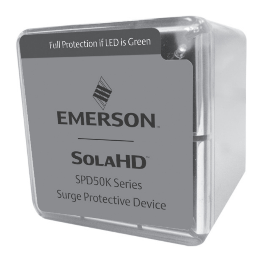
- Page 1 Surge Protective Devices SPD50K Series...
-
Page 2: Safety Information
SPD50K Safety Information Important Information Read these instructions carefully and look at the equipment to become familiar with the device before trying to install, operate, service or maintain it. The following special messages may appear throughout this bulletin or on the equipment to warn of potential hazards or to call attention to information that clarifies or simplifies a procedure. - Page 3 SPD50K Precautions DANGER HAZARD OF ELECTRIC SHOCK, EXPLOSION, OR ARC FLASH • Apply appropriate personal protective equipment (PPE) and follow safe electrical work practices. See NFPA 70E, NOM-029-STPS or CSA Z462. • This equipment must only be installed and serviced by qualified electrical personnel. •...
-
Page 4: Unpacking And Preliminary Inspection
SPD50K DANGER HAZARD OF ELECTRIC SHOCK, EXPLOSION, OR ARC FLASH • Do not energize the surge protective device until the electrical system is completely installed, inspected and tested. • Ensure all conductors are connected. • Verify the voltage rating of the device and system prior to energizing. •... -
Page 5: Identification Nameplate
SPD50K Storage The device should be stored in a clean, dry environment. Storage temperature is -67 °F to +149 °F (-55°C to +65°C). All of the packaging materials should be left intact until the device is ready for installation. Identification Nameplate The identification nameplate is located on the side of the unit. -
Page 6: Equipment Performance
SPD50K Equipment Performance To obtain optimum surge suppression, locate the SPD as close as possible to the circuitry being surge-limited to minimize the wire length. Minimizing the wire length reduces the impedance between the circuitry and the SPD. Refer to the Voltage Protection Rating (VPR) values on the SPD nameplate. These VPR values were obtained by testing the SPD with six-inch long leads (per UL1449). -
Page 7: Voltage Rating
SPD50K Dimensions (in./mm) (L-BRACKET IS INCLUDED) Electrical DANGER HAZARD OF ELECTRIC SHOCK, EXPLOSION, OR ARC FLASH • Confirm the surge protective device voltage rating on the module or nameplate label is not less than the operating voltage. Failure to follow these instructions will result in death or serious injury. Voltage Rating Prior to mounting the SPD, verify that the device has the same voltage rating as the power distribution system in which it is installed. - Page 8 SPD50K Table 1: Model SPD50K Service Voltages Surge Protective Device 50kA Rating Per Phase Voltage Codes 10S – 120V/240V 10Y – 208Y/120V 27Y – 480Y/277V 24D – 240V Delta 48D – 480V Delta 34Y – 600Y/347V 60D – 600V Delta System Reference Configuration...
- Page 9 SPD50K Location of Surge Protective Device (SPD) UL 1449 Type 1 SPDs have been designed and approved for line side applications prior to the main service dis- connect without supplemental overcurrent protection. Type 2 SPDs must be installed on the load side of the main Overcurrent Protective Device (OCPD).
-
Page 10: System Grounding
SPD50K Figure 3: SPD Wiring for Delta Configurations To load(s) Phase A Phase B Phase C Phases Ground Ground Interconnect wiring – Minimize length – Avoid sharp bends System Grounding CAUTION SPD DAMAGE AND POWER SYSTEM OVER VOLTAGE • Ungrounded power systems are inherently unstable and can produce excessively high line-to-ground voltages during certain fault conditions. -
Page 11: Wiring And Installation
SPD50K NOTICE INADEQUATE RACEWAY ELECTRICAL CONTINUITY • Install an insulated grounding conductor inside a metallic raceway when the raceway is used as an additional grounding conductor. Size the conductor in accordance with all applicable codes. • Maintain adequate electrical continuity at all raceway connections. •... - Page 12 SPD50K Table 2: Wire Color Wye and Delta Systems Wire Color Phase 1-3 Black Neutral White Ground Green Delta Systems Wire Color Phase 1-3 Black Ground Green Follow steps 1 through 10 to make wiring connections: 1. Turn off all power supplying this equipment before working on or inside any enclosure containing this equipment.
- Page 13 SPD50K Figure 4: Nipple Sealing gasket: Two choices 1) At 3/4 in. nom. thread: ID is 1.05 in. 2) At 0.14 in. high 'base step': ID is 1.25 in. Figure 5: Typical panel Installation (Type 1 or individual equipment installations may vary) To Protected Loads Use closest breaker to SPD Locate SPD close to intended...
- Page 14 SPD50K Figure 6: Single-Phase, Three-Wire Installation Black Phase A (Black) White Neutral (White) Black Phase B (Black) Ground (Green) Green Figure 7: Three-Phase, Three- or Four-Wire, Grounded WYE Installation Black Phase A (Black) Phase B (Black) Black Neutral (White) White Phase C (Black) Black Ground (Green)
-
Page 15: Surface-Mount Installation
SPD50K Figure 9: Mounting the SPD50K 3/4" pipe nipple (conduit nut included) • With L-bracket mounting kit accessory • - Standard 35mm DIN-Rail (not included) L-bracket tightens onto DIN-Rail • - Standard flat mounting surface Attach L-bracket to surface via mounting holes •... -
Page 16: Operation
SPD50K Operation DANGER HAZARD OF ELECTRIC SHOCK, EXPLOSION, OR ARC FLASH • Apply appropriate personal protective equipment (PPE) and follow safe electrical work practices. See NFPA 70E, NOM-029-STPS or CSA Z462. • This equipment must only be installed and serviced by qualified electrical personnel. •... -
Page 17: Dry Contacts
SPD’s relay caused by use with energy levels in excess of those discussed in this instruction bulletin are not covered by warranty. For application questions, call the SolaHD technical support at 1-800-377-4384 or email us at solahd.technicalservices@emerson.com. Three 3 ft. (~1 m) 18 AWG wires are included through the nipple with this option. See Figure 12. Gray is Common, Blue is Normally Open and Red is Normally Closed when energized in its expected installation. -
Page 18: Preventive Maintenance
SPD50K Figure 11: Leads Normally Closed (suggested): Use Gray and Red • Normally Open: Use Gray and Blue • Blue Gray Preventive Maintenance DANGER HAZARD OF ELECTRIC SHOCK, EXPLOSION, OR ARC FLASH • Apply appropriate personal protective equipment (PPE) and follow safe electrical work practices. See NFPA 70E, NOM-029-STPS or CSA Z462. -
Page 19: Technical Support
SPD50K Technical Support Website: www.solahd.com Technical Support E-Mail: solahd.technicalservices@emerson.com Toll-Free: (800) 377-4384 USA: (847) 268-6651 Warranty Please see the “Terms & Conditions of Sale” document. While every precaution has been taken to ensure accuracy and completeness in this manual, Appleton Grp LLC d/b/a Appleton Group assumes no responsibility, and disclaims all liability for damages resulting from use of this information or for any errors or omissions. - Page 20 The Emerson logo is a trademark and service mark of Emerson Electric Co. Appleton Grp LLC d/b/a Appleton Group. SolaHD is a registered trademark of Appleton Grp LLC. All other marks are the property of their respective owners. © 2021 Emerson Electric Co. All rights reserved. United States...
Need help?
Do you have a question about the SolaHD SPD50K Series and is the answer not in the manual?
Questions and answers