
Related Manuals for Hioki 8910


Summary of Contents for Hioki 8910
- Page 1 8910 Instruction Manual CAN ADAPTER Aug. 2018 Revised edition 7 8910A981-07 18-08H...
-
Page 3: Table Of Contents
Contents Contents Introduction.................1 Inspection ...................1 Safety Notes................4 Notes on Use................7 Chapter 1 Product Overview __________________________ 11 Overview ..............11 Major Features ............12 Identification of Controls and Indicators ......13 Chapter 2 Preparation ________________________________ 15 Installation of the Instrument ........15 Power Supply Connections .........16 2.2.1 Connecting the AC adapter ...........16 2.2.2... - Page 4 Un-Installation ............... 39 Chapter 5 Starting the CAN Set Program ________________ 41 Connecting the PC to the 8910 ........41 Starting Up the Condition Setting Program ....42 Menu Items in the Setting Window ......45 Operation Flowchart ........... 46...
- Page 5 Setting the message ID trigger ........79 7.3.2 Setting output channels ..........80 Setting the ID Filter .............81 Chapter 8 Transfer of Setting Data to the 8910 ___________ 83 Setting Communication Parameters ......83 Executing Data Transfer ..........84 In Case of Errors ............85 Duplicate Bit Check .............86...
- Page 6 Contents Chapter 10 Connection to Memory HiCorder ______________ 95 10.1 Using the 8910 with the 8826 MEMORY HiCORDER 96 10.1.1 Displaying the 8910 setting screen ....... 96 10.1.2 8910 setting screen ............98 10.1.3 Setting the block no............99 10.1.4 Setting analog channel output ........
- Page 7 Contents Chapter 12 Maintenance and Service ___________________ 135 12.1 Service and Cleaning ..........135 12.2 Troubleshooting ............135...
- Page 8 Contents...
-
Page 9: Introduction
Introduction Introduction Thank you for purchasing the HIOKI “Model 8910 CAN ADAPTER”. To obtain maximum performance from the instrument, please read this manual first, and keep it handy for future reference. Inspection When you receive the instrument, inspect it carefully to ensure that no... - Page 10 Inspection Power cord ..........1 9713-01 CAN CABLE (one end unprocessed) (Approx. 2 m) ...... 1 Options 9713-01 CAN CABLE (one end unprocessed) (Approx. 2 m) 9713-02 CAN CABLE (For automotive connector) (Approx. 2 m) (Since this part is made to order, check the specifications document and delivery date.) 9714-01 LOGIC CABLE (one end unprocessed) (Approx.
- Page 11 Before using the instrument the first time, verify that it operates normally to ensure that the no damage occurred during storage or shipping. If you find any damage, contact your dealer or Hioki representative. Before using the instrument, make sure that the insulation on the cords and cables are undamaged and that no bare conductors are improperly exposed.
-
Page 12: Safety Notes
Safety Notes Safety Notes This instrument is designed to comply with IEC 61010 Safety Standards, and has been thoroughly tested for safety prior to shipment. However, mishandling during use could result in injury or death, as well as damage to the instrument. Be certain that you understand the instructions and precautions in the manual before use. - Page 13 Safety Notes Mouse Operation Click Press and quickly release the left button of the mouse. Right-click Press and quickly release the right button of the mouse. Double click : Quickly click the left button of the mouse twice. Drag While holding down the left button of the mouse, move the mouse and then release the left button to deposit the chosen item in the desired position.
- Page 14 Safety Notes Measurement categories To ensure safe operation of measurement instruments, IEC 61010 establishes safety standards for various electrical environments, categorized as CAT II to CAT IV, and called measurement categories. These are defined as follows. CAT II : Primary electrical circuits in equipment connected to an AC electrical outlet by a power cord (portable tools, household appliances, etc.) CAT II covers directly measuring electrical outlet receptacles.
-
Page 15: Notes On Use
(2) When powering the 8910 from a DC power source, before making other connections, first connect the ground of the 8910 to the grounds of the devices to be connected. In this case, always use the same power source. 2.2.2 Connecting the DC Power Supply (Page 17) and 2.3 Connection Procedure (Page 18) - Page 16 Never use abrasives or solvent cleaners. • Hioki shall not be held liable for any problems with a computer system that arises from the use of this CD-R, or for any problem...
- Page 17 • Carefully read and observe all precautions in this manual. • Using an connection cord other than that specified by HIOKI may damage the BNC connector or result in measurement errors due to contact failure.
- Page 18 Notes on Use...
-
Page 19: Chapter 1 Product Overview
• The type of data to be acquired is set by using a PC, with settings transferred and saved in internal memory of the 8910 via the RS- 232C. • Internal memory can store up to 50 items of CAN definition data. -
Page 20: Major Features
The main unit is compact and lightweight for easy portability. 2. Ample output channels The 8910 is equipped with ample output channels - 12 channels for analog signal output and 24 bits for logic signal output. 3. Two independent input ports Since CAN1 and CAN2 are independent, two networks with different baud rates can be connected. -
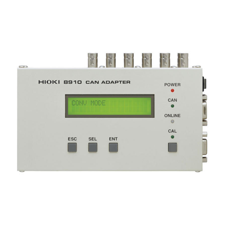
Page 21: Identification Of Controls And Indicators
OFFLINE switch is set to the ONLINE side for ON status of the instrument. enabling communication. The LED goes on in red when The LED goes on in orange when the 8910 is power is turned on. engaged in communication. CAN LED... - Page 22 (A DC power supply (10 to 30 V) can also be ONLINE enables the 8910 to communicate connected.) with the host PC or Memory HiCorder. ONLINE/OFFLINE Key lock: Note that the 8910 accepts no key entry when the [ ] switch is set to the ONLINE ] side.
-
Page 23: Chapter 2 Preparation
2.1 Installation of the Instrument Chapter 2 Preparation 2.1 Installation of the Instrument 1. Installation orientation Install the instrument on a flat, level surface. 2. Ambient conditions • Temperature : -10 to 55°C • Humidity : 30 to 80%RH (with no condensation) 3. -
Page 24: Power Supply Connections
• To avoid electrical accidents and to maintain the safety specifications of this instrument, connect the power cord only to a 3-contact (two-conductor + ground) outlet. Connect the AC adapter to the 8910. Connect the AC adapter plug to an outlet. -
Page 25: Connecting The Dc Power Supply
2.2 Power Supply Connections 2.2.2 Connecting the DC Power Supply In addition to the AC adapter, any of the following power sources can be used: • DC power supply (10 to 30 V) (Voltage fluctuations of ±10% from the rated supply voltage are taken into account.) •... -
Page 26: Connection Procedure
8910. • The ground (GND) conductors of connecting cables connect in common to the Model 8910 chassis ground (they are not isolated). Therefore, supplying power from different sources to the instrument and a connecting device could cause electric shock and equipment damage. - Page 27 8910 from DC and connecting devices from AC) Before making other connections to the 8910, first connect the ground of the 8910 to the grounds of the devices to be connected. Refer to the following alternatives regarding common ground connection methods.
- Page 28 Therefore, when only one device connected to the bus in addition to the 8910, communication is not possible since response bits cannot be exchanged. Therefore, be sure to connect the bus to which the 8910 is connected with two or more devices to enable communication.
-
Page 29: Power On/Off
Check the following points before the power switch is turned on. • When using the AC adapter, make sure that the power supply complies with the rated voltage (100 - 240 VAC) and rated frequency (50/60 Hz) of the 8910. • The instrument is correctly connected. (Section 2.1, 15p.) Connect the cables and cords. - Page 30 2.4 Power On/Off • The error message continues flashing until a key is pressed. • While the error message is displayed, RS communication is disabled. To conduct RS communication, press any key to place the instrument in conversion mode.
-
Page 31: Chapter 3 Operation
When conversion mode is active, the LCD indicates the following: CONV MODE • The 8910 monitors the CAN bus and adjusts the baud rate automatically. Therefore, the instrument has already begun to receive signal input from CAN1 or CAN2 at this point. -
Page 32: Setting Mode
• This mode is used to set the data to be output from each analog/ logic output channel. • The internal memory of the 8910 can store up to 50 items of CAN definition data. • The data in memory can be assigned to the 12 analog output channels or six (24 bits) logic output channels for output. -
Page 33: Activating Setting Mode
3.3.1 Activating setting mode Position the [ONLINE/OFFLINE] switch to the [OFFLINE] side. To use the keys on the 8910 for entering settings, position the [ONLINE/OFFLINE] switch to the [OFFLINE] side. Make sure that the ONLINE LED is off Press the [SEL] key. -
Page 34: Contents Of Display In Setting Mode
3.3 Setting Mode 3.3.2 Contents of display in setting mode When the data to be output is assigned, the label name and D/A conversion format ([B] or [M]) of CAN definition data are indicated for an analog channel; the label name and bit position are indicated for a logic channel. -
Page 35: Selecting The Can Definition Data To Be Output
3.3 Setting Mode 3.3.4 Selecting the CAN definition data to be output Enter the channel number. (Section 3.3.3, 26p.) When the [ENT] key is pressed to enter the channel number, the channel number stops flashing. At the same time, the label name of CAN definition data starts flashing, indicating that CAN definition data assigned to the output channel can be changed. -
Page 36: Setting The D/A Conversion Format/Logic Bit Position
3.3 Setting Mode 3.3.5 Setting the D/A conversion format/logic bit position Enter the CAN definition data. (Section 3.3.4, 27p.) When CAN definition data is entered by pressing the [ENT] key, the D/A conversion format ([B] or [M]) flashes for an analog channel; the bit position flashes for a logic channel. -
Page 37: Returning To Conversion Mode
3.3.6 Returning to conversion mode After settings are made, press the [ESC] key several times to return to conversion mode. When no key entry is made for about 30 seconds, the 8910 also returns to conversion mode. -
Page 38: Calibration Mode
3.4.1 Activating calibration mode Position the [ONLINE/OFFLINE] switch to the OFF LINE side. To use the keys on the 8910 for entering settings, position the [ONLINE/OFFLINE] switch to the [OFFLINE] side. Make sure that the ONLINE LED is off. Press the [SEL] key. -
Page 39: Selecting A Channel Number
3.4 Calibration Mode 3.4.2 Selecting a channel number Activating calibration mode. (Section 3.4.1, 30p.) When calibration mode is activated, the channel number on the LCD flashes, indicating that channel selection can be changed. Calibration A01 Push the [SEL] key, and select a channel. In this condition, each time the [SEL] key is pressed, the channel indicated on the LCD changes sequentially from analog channel 1 to 12. -
Page 40: Returning To Conversion Mode
3.4 Calibration Mode 3.4.4 Returning to conversion mode • Press the [ESC] key to exit from calibration mode and return to conversion mode. • When no key entry is made for about 30 seconds, the 8910 also returns to conversion mode. -
Page 41: Operation Map
SYSTEM RESETモード Analog 01 While pressing the [ESC] key, [SEL] key, and [ENT] key Speed B simultaneously, turn on the power switch of the 8910. This will place the instrument in system reset mode. Press the [ENT] key to SYSTEM RESET reset the system. - Page 42 In ONLINE mode, RS communication is enabled. The keys are not operable in this mode (key lock). In OFFLINE mode, the 8910 accepts operations. RS communication is not possible in this mode. RS communication Even when the instrument is in ONLINE mode, the ONLINE LED goes off and RS communication is disabled in the following cases: 1.
- Page 43 Therefore, the setting is written to backup memory at this time. If 8910 power is turned off before setting item selection returns to the channel selection, the setting change made in setting mode will not be written to backup memory.
- Page 44 3.5 Operation Map...
-
Page 45: Preparation Of The Can Set Program
This mode is used to set the 8910 CAN ADAPTER. In this mode, up to 50 items of CAN definition data to be registered in the 8910 can be selected, with data to be output from the 8910 output channel selected from the data registered. After setting is completed, the setting data is transferred to the 8910 via the RS-232C. -
Page 46: Program Setup
4.2 Program Setup 4.2 Program Setup 4.2.1 System requirements To use the program, the following hardware and software are required: Personal computer IBM PC/AT compatible Pentium 133 MHz or higher (recommended) Min. 64 MB RAM (recommended) Free hard disk space: 5 MB RS-232C capability CD-ROM drive (to install software) Microsoft Windows 95 (OSR2 or later) -
Page 47: Un-Installation
4.2.3 Un-Installation The program can be uninstalled by using one of the following methods: <Method 1> Click the [Start] button to open the Windows Start Menu. − Select [Programs] - [HIOKI] [8910 CanSet Program] - [Uninstall 8910 CanSet Program]. When a dialog box appears asking about file deletion, select [Yes]. - Page 48 4.2 Program Setup...
-
Page 49: Starting The Can Set Program
Starting the CAN Chapter 5 Set Program Before initiating the setting procedure, connect the PC to the 8910. After connection is made, start up the setting application software. 5.1 Connecting the PC to the 8910 Follow the procedure below to connect the PC to the 8910. -
Page 50: Starting Up The Condition Setting Program
[8910 CanSet Program] - [8910 CanSet Program]. The program starts up and the following 8910 setting window appears on the display. <To end the program> Select [Close] or [Exit] on the [File] pull-down menu. Selecting [Close] only closes the 8910 setting window. Selecting [Exit] closes the 8910 setting window and CAN definition data editing window (Section 6.6, 65p.) at the same time. - Page 51 Each input port can be set with a filter to prevent the reception of messages in standard or extended format. 9. 8910 registration list edit button This button is used for editing an 8910 registration list. It allows the editing of an existing list and creation of a new list.
- Page 52 5.2 Starting Up the Condition Setting Program 14. Status bar This section indicates the current status. Checking [Status bar] on the [View] pull-down menu displays the status bar.
-
Page 53: Menu Items In The Setting Window
(Section 5.2, 42p.) (Section 9.4, 93p.) [Modify Password] [Send] (Section 8.2, 84p.) [Settings] (Section 8.1, 83p.) [Toolbar] (Section 5.2, 42p.) [Status bar] (Section 5.2, 42p.) [Cascade] (Section 9.3, 92p.) [Tailed] (Section 9.3, 92p.) [About 8910 Can Set] (Section 9.5, 94p.) -
Page 54: Operation Flowchart
5.4 Operation Flowchart 5.4 Operation Flowchart 1. Prepare for setting. • Connecting the PC to the 8910 Connect the PC to the 8910 via the RS-232C. • Starting up the 8910 CAN set program 2. Set the CAN definition data. - Page 55 5.4 Operation Flowchart 7. Send the set data to the 8910. • Setting communication parameters Set the communication parameters on the PC. • Transmission of data Transfer the data to the 8910. • Storage of set data 8. Record the setting data.
- Page 56 5.4 Operation Flowchart...
-
Page 57: Setting The Can Definition Data
• Parameters must be edited or created to acquire data from the CAN bus. • CAN definition data can be set using the 8910 setting window or by opening the CAN definition data editing window. The following describes how to set data in the 8910 setting window. -
Page 58: Creating A New Can Definition Data File
6.1 Opening a CAN definition data file 6.1.2 Creating a new CAN definition data file Click [Edit] button. Click the button located above the CAN definition data list to create a new CAN definition data file. To prevent operation errors, only the [Edit] button is operable under normal conditions. - Page 59 6.1 Opening a CAN definition data file Click the [New] button. Clicking the [New] button opens a confirmation dialog box that asks whether to initialize the CAN definition data file. Creates a CAN definition data file. Cancel Cancels creation of a CAN definition data file. Clicking [OK] deletes the content of the currently displayed CAN definition data list and executes initialization.
-
Page 60: Editing The Can Definition Data
6.2 Editing the CAN Definition Data 6.2 Editing the CAN Definition Data New definition data can be added to the currently open CAN definition data file. Click the [Add] button. Click the [Add] button located above the CAN definition data list to open the CAN definition data setting window. -
Page 61: Setting The Message Id
Enter the size (bits) of data to be acquired. • Since the maximum size of data that can be captured by the 8910 is 2 bytes (16 bits), a value from 1 to 16 can be entered in the input box. -
Page 62: Setting The Data Start Position
6.2 Editing the CAN Definition Data 6.2.3 Setting the data start position The least significant bit (LSB) position of acquisition data is used to specify its location in the CAN data frame. The bit positions are numbered as follows: As the reference position, the least significant bit (LSB) position of the first byte of data in the data frame is given a value of 0. -
Page 63: Setting The Data Pattern
6.2 Editing the CAN Definition Data 6.2.4 Setting the data pattern Here, the data pattern is set. Even if the data start position and data length are the same, the data position (method of data acquisition) varies depending on whether the data pattern is Motorola format or Intel format. -
Page 64: Setting The Sign
6.2 Editing the CAN Definition Data Example: In the 16-bit data shown in the diagram, when the value of Byte 0 is FF and the value of Byte 1 is 00, the following value results according to the method used: →... -
Page 65: Setting The Signal Name
A comment can be entered as the signal name. • When the 8910 CAN ADAPTER is used with the HIOKI 8826, 8841, 8842 MEMORY HiCORDER, the signal name can be transferred to the 8826, 8841, 8842 MEMORY HiCORDER as comment data. -
Page 66: Setting The Scaling
• However, this setting is useful for understanding the possible range of physical quantity of actual data. • When the 8910 CAN ADAPTER is used with the HIOKI 8826, 8841, 8842 MEMORY HiCORDER, the scaling setting on the 8826, 8841, 8842 MEMORY HiCORDER side can be automatically adjusted according to the value set here. - Page 67 6.2 Editing the CAN Definition Data When the [BitRate] or [Offset] is set, the [Maximum] and [Minimum] values are automatically set based on the set values, data length setting, and sign setting. Specifying with maximum and minimum values Select the radio button next to [Minimum]. Select the radio button next to [Minimum] when using the maximum and minimum values to specify the scaling Set the [Maximum] and [Minimum] value.
-
Page 68: Error Massage
6.2 Editing the CAN Definition Data 6.2.10 Error Massage If the CAN definition data settings are incorrect or conflicting, an error message appears when the [OK] button is clicked. If an error message appears, take the following corrective action: If error message " "... -
Page 69: Deletion Of Can Definition Data
6.3 Deletion of CAN Definition Data 6.3 Deletion of CAN Definition Data The definition data in the current CAN definition data file can be deleted as follows: Click the [Del] button. When the definition data to delete is selected in the CAN definition data list and the [Del] button located above the list clicked, the deletion confirmation dialog box opens. -
Page 70: Closing The Can Definition Data File (Saving The File)
6.4 Closing the CAN Definition Data File (Saving the File) 6.4 Closing the CAN Definition Data File (Saving the File) Click the [Edit] button. To close the currently open CAN definition data file, click the depressed [Edit] button. Click the [OK] or [Cancel] button. If the content of the CAN definition data file has been changed, a dialog box appears, asking whether to save the changes you made. -
Page 71: Can Definition Data List Detail Display
6.5 CAN Definition Data List Detail Display 6.5 CAN Definition Data List Detail Display The CAN definition data list usually shows only five items (as follows) due to limited space: • Number • Signal name • Label name • Unit •... - Page 72 Move the cursor, and left-click the mouse. Position the cursor on the border between the CAN definition data list and 8910 registration list so that the cursor changes into a double arrow pointing left and right. Then, left-click the mouse.
-
Page 73: Editing In Another Window
6.6 Editing in Another Window 6.6 Editing in Another Window In addition to the 8910 setting window, the CAN definition data editing window can be used for setting CAN definition data. 6.6.1 Opening a new window Select [File] - [CAN Define Data File]. - Page 74 Clicking color icons on the toolbar executes the following operations: The icons effective in this window are (from the left): • [New] for the 8910 setting file • [Open] for the 8910 setting file • [New] for the CAN definition data file •...
- Page 75 <To End> Select [Close] or [Exit] on the [File] pull-down menu. Selecting [Close] only closes the CAN definition data editing window. Selecting [Exit] closes the CAN definition data editing window and 8910 setting window (Section 5.2, 42p.) at the same time.
- Page 76 [Print Preview] mode. [Print Setup] (Section 9.2.3, 90p.) [Exit] (Section 6.6.1, 65p.) (Section 9.4, 93p.) [Modify Password] [Toolbar] (Section 6.6.1, 65p.) [Status bar] (Section 6.6.1, 65p.) [Cascade] (Section 9.3, 92p.) [Tailed] (Section 9.3, 92p.) [About 8910 Can Set] (Section 9.5, 94p.)
-
Page 77: Creating A New Can Definition Data File
6.6 Editing in Another Window 6.6.2 Creating a new CAN definition data file Select [New] on the [File] pull-down menu or click the following icon on the toolbar to create a new CAN definition data file. 6.6.3 Opening a CAN definition data file Select [Open] on the [File] pull-down menu or click the following icon on the toolbar to open another CAN definition data file. - Page 78 6.6 Editing in Another Window...
-
Page 79: Chapter 7 Settings
• Label name • Unit • Data length Up to 50 items of CAN definition data can be registered on the 8910. 7.1.1 Opening a registration list Select [file] - [Open] or clicking the icon Select [Open] on the [File] pull-down menu or click the icon on the toolbar to download a stored 8910 setting file. -
Page 80: Creating A Registration List (Registering Definition Data To A Registration List)
Select [File] - [New] or click the icon Selecting [New] on the [File] pull-down menu or clicking the following icon on the toolbar deletes and initializes the contents of the 8910 registration list and analog/logic output allocation list. When the registered contents already exist, a confirmation dialog box appears prior to deletion. - Page 81 Registering from the CAN definition list to the 8910 registration list The highlighted line in the CAN definition list can be added to the 8910 registration list by dragging and dropping, or by clicking the [Add] button above the 8910 registration list.
-
Page 82: Deleting Data From The Registration List
Cancel Stops the registration of data in the list. The items (up to 50) registered in the 8910 registration list are sent to the memory of the 8910. 7.1.3 Deleting data from the registration list Click an item. -
Page 83: Allocation To Output Channels
7.2 Allocation to Output Channels 7.2 Allocation to Output Channels 7.2.1 Setting analog output channels The data to be acquired by the 8910 must be selected from items registered in the 8910 registration list, and a channel must be selected to output that data. -
Page 84: Deleting Registered Data From The Analog Output Allocation List
7.2 Allocation to Output Channels Select [B(+/-)] or [M(+)]. After allocation is completed, the D/A conversion format setting dialog box opens. Select bipolar or monopolar. This setting determines ± whether the analog signal is output in a 5 V range or 0 to 5 V range. Section 3.3.5, (28p.) B(+/-) ±... -
Page 85: Setting Logic Output Channels
7.2 Allocation to Output Channels 7.2.3 Setting logic output channels Logic output channels are set the same way as for analog output channels. Section 7.2.1, (75p.) When assigned data is 2 bits or larger, the data is automatically allocated so that the most significant bit is assigned to the channel selected, with the rest allocated to the following channel. -
Page 86: Deleting Data From The Logic Output Allocation List
7.2 Allocation to Output Channels 7.2.4 Deleting data from the logic output allocation list Select an item to be deleted, and right-click. When an item to be deleted from the logic output allocation list is right- clicked. Click [Yes]. A dialog box appears, asking whether to delete the data. Click [Yes] to delete the selected line. -
Page 87: Massage Id Trigger
Therefore, setting the ID trigger does not allow you to observe the output pulse even when a logic output is held H. In such case, turn off the power of the 8910, then turn it back on and set the logic output to L before setting the ID trigger. -
Page 88: Setting Output Channels
7.3 Massage ID Trigger 7.3.2 Setting output channels Multiple logic channels can be specified for ID trigger output. Double-click a logic channel. Double-clicking a logic channel to be specified as an output channel changes the corresponding icon to red and sets the channel as an output channel. -
Page 89: Setting The Id Filter
7.4 Setting the ID Filter 7.4 Setting the ID Filter Individual input ports can be applied with a filter to inhibit the reception of messages other than those assigned to the output channels. • The filter results in the acquisition of standard format or extended format only. - Page 90 7.4 Setting the ID Filter...
-
Page 91: Transfer Of Setting Data To The 8910
8.1 Setting Communication Parameters Transfer of Setting Data Chapter 8 to the 8910 The CAN definition data registered in 8910 registration data, and the analog/logic channel allocation settings can be transferred to the 8910. 8.1 Setting Communication Parameters Select [Comm] - [Settings]. -
Page 92: Executing Data Transfer
8.2 Executing Data Transfer Make sure that the 8910 is connected to the PC. Make sure that the CAN1 and CAN2 ports on the 8910 are not connected to any cable. Set the 8910 to ONLINE mode. (Position the [online/offline] switch to [ONLINE] side.) -
Page 93: In Case Of Errors
• Is a logic channel set for signal output? If an error occurs, the 8910 may remain in Remote mode (with the ONLINE LED lit in orange). In this case, retransmit the data to exit Remote mode. -
Page 94: Duplicate Bit Check
If duplicate bits are found, the following items are displayed. • Registration list item no. • Massage ID • Signal name of the duplicate data The transfer operation can be resumed or cancelled. Transfer data to the 8910. Cancel Cancels data transfer to the 8910. -
Page 95: Functions Of The Setting Program
9.1 Saving the Setting Data The settings can be saved on a specified destination media. 9.1.1 Saving data with a new name The data edited in 8910 setting mode can be saved with a new name by selecting [Save as] on the [File] pull-down menu or clicking the icon below on the toolbar. -
Page 96: Overwriting
9.1 Saving the Setting Data 9.1.2 Overwriting The current setting data can be written over an existing 8910 setting file by selecting [Save] on the [File] pull-down menu or clicking the icon below on the toolbar. If the current list has no file name, such as for a newly created file,... -
Page 97: Setting Data Printout
9.2 Setting Data Printout 9.2.1 Printing The content of 8910 setting data can be printed by selecting [Print] on the [File] pull-down menu or clicking the icon below on the toolbar. The printed information includes the contents of the 8910 registration list and analog/logic output allocation list. -
Page 98: Setting The Printer
9.2 Setting Data Printout 9.2.3 Setting the printer Select [Printer Setup] on the [File] pull-down menu to set printer conditions. 9.2.4 Examples of printouts... - Page 99 9.2 Setting Data Printout...
-
Page 100: Displaying Windows
9.3 Displaying Windows When the CAN definition data setting window is opened, it appears on top of the 8910 setting window. Both windows can be repositioned for easy viewing by selecting [Cascade] or [Tiled] on the [Window] pull- down menu. -
Page 101: Password Setting
9.4 Password Setting 9.4 Password Setting • The password protection function can be activated, requiring the set password to be entered for opening a CAN definition data file. • This function effectively prevents the inadvertent editing of data. Select [Edit] - [Modify Password]. To set a password, select [Modify Password] on the [Edit] pull-down... -
Page 102: Version Check
9.5 Version Check 9.5 Version Check • You will be asked to provide the software version no. when making an inquiry regarding the product. • To check the software version, select [About 8910 Set] on the [Help] pull-down menu. -
Page 103: Connection To Memory Hicorder
Memory Chapter 10 HiCorder The 8910 can be connected to the 8826, 8841, or 8842 MEMORY HiCORDER via the RS-232C interface for the transfer of 8910 setting data to and from the Memory HiCorder. The Memory HiCorder enable as follows: •... -
Page 104: Using The 8910 With The 8826 Memory Hicorder
10.1 Using the 8910 with the 8826 MEMORY HiCORDER 10.1 Using the 8910 with the 8826 MEMORY HiCORDER 10.1.1 Displaying the 8910 setting screen Display [SYSTEM 4 - INTERFACE] screen on the 8826. Press the [SYSTEM] key of the 8826 until the [SYSTEM4- INTERFACE] screen is shown. - Page 105 SET] key switches display from the interface setting screen to the 8910 setting screen. <8910 Setting Screen> <To switch the screen> To switch from the 8910 setting screen to the interface setting screen, click the [CH. SET] key while the [INTERFACE] GUI is displayed next to the [CH.
-
Page 106: 8910 Setting Screen
10.1 Using the 8910 with the 8826 MEMORY HiCORDER 10.1.2 8910 setting screen Item Description Reference Used to select a block for saving 1. Block no. setting 10.1.3 setting data. Used to set and display CAN definition 2. Analog CH output data to be output from an analog 10.1.4... -
Page 107: Setting The Block No
10.1 Using the 8910 with the 8826 MEMORY HiCORDER 10.1.3 Setting the block no. • The 8826 can store the setting data of up to six 8910s. Each setting data storage area is called a block. • Move the flashing cursor to the [BLOCK NO.] indication, then use a... -
Page 108: Setting Analog Channel Output
8910. This 4. 8826 input 1 to 32 channel information is required to reflect the scaling value and signal name on the 8826. Setting changes made here are not reflected on the 8910 until data transmission (Section 10.1.7, 104p.) is performed. - Page 109 10.1 Using the 8910 with the 8826 MEMORY HiCORDER • The [F3] (Scaling function key) is effective for items 2 to 4 above. Clicking this function key automatically sets the scaling value for the channel specified as the 8826 input channel according to the content of CAN definition data as follows: •...
-
Page 110: Setting Logic Channel Output
4. 8826 input the 8910. This information is required A1 to H4 channel to reflect the scaling value and signal name on the 8826. Setting changes made here are not reflected on the 8910 until data transmission (Section 10.1.7, 104p.) is performed. -
Page 111: Displaying The Registration List
10.1.6 Displaying the registration list The CAN definition data downloaded into blocks can be displayed. On the 8910 setting screen, the [LIST] GUI is shown next to the [VIEW] key. In this state, pressing the [VIEW] key switches display in the following... -
Page 112: Communication Between The 8826 And 8910
10.1 Using the 8910 with the 8826 MEMORY HiCORDER Setting display items of scaling (from left) Label name up to 16 alphanumeric characters Bit rate decimal value (exponential notation) Offset decimal value (exponential notation) Unit up to 8 characters <Example of CAN definition data setting list display>... - Page 113 Follow the procedure below to receive data. Connect the 8826 to the 8910 with the RS-232C cable. Position the [ONLINE/OFFLINE] switch of the 8910 to [ONLINE] side. On the 8910 setting screen of the 8826, select a block to receive data, → then click [F4] (8910 RECORDER function key).
- Page 114 Connect the 8826 to the 8910 with the RS-232C cable. Position the [ONLINE/OFFLINE] switch of the 8910 to [ONLINE] side. On the 8910 setting screen of the 8826, select a block to which to → send data, then click [F5] (RECORDER 8910 function key).
-
Page 115: Downloading An Setting Data File
An 8910 setting data file (with extension "cmu") created with the “8910 CAN set program” software can be downloaded to the 8826. Select a block. Open the 8910 setting screen and select a block to which to transfer the setting data. Download the 8910 setting data file. - Page 116 10.1 Using the 8910 with the 8826 MEMORY HiCORDER The setting data is transferred to the selected block. Note that executing the data read command deletes all existing data in the block.
-
Page 117: Using The 8910 With The 8841, 8842 Memory Hicorder
10.2 Using the 8910 with the 8841, 8842 MEMORY HiCORDER 10.2 Using the 8910 with the 8841, 8842 MEMORY HiCORDER 10.2.1 Displaying the 8910 setting screen Display [SYSTEM 4 - INTERFACE] screen on the 8841, 8842 Press the [SYSTEM] key of the 8841, 8842 until the [SYSTEM4- INTERFACE] screen is shown. - Page 118 SET] key switches display from the interface setting screen to the 8910 setting screen. <8910 Setting Screen> <To switch the screen> To switch from the 8910 setting screen to the interface setting screen, click the [CH. SET] key shown next to the [INTERFACE] GUI.
-
Page 119: 8910 Setting Screen
10.2 Using the 8910 with the 8841, 8842 MEMORY HiCORDER 10.2.2 8910 setting screen Item Description Reference Used to select a block for saving 1. Block no. setting 10.2.3 setting data. Used to set and display CAN definition 2. Analog CH output data to be output from an analog 10.2.4... -
Page 120: Setting The Block No
10.2 Using the 8910 with the 8841, 8842 MEMORY HiCORDER 10.2.3 Setting the block no. • The 8841, 8842 can store setting data of up to six 8910s. Each setting data storage area is called a block. • Move the flashing cursor to the [BLOCK NO.] indication, then use a... -
Page 121: Setting Analog Channel Output
10.2 Using the 8910 with the 8841, 8842 MEMORY HiCORDER 10.2.4 Setting analog channel output • The setting items are shown below. • The cursor keys can be used to move the cursor to any item indication except those in the 8910 CH column. - Page 122 : Offset - BitRate / 2.0 For monopolar × Conversion bit rate : ((2 BitRate) / 5.0 × Offset : Offset - 2 BitRate Setting changes made here are not reflected on the 8910 until data transmission (Section 10.2.7, 117p.) is performed.
-
Page 123: Setting Logic Channel Output
• The [F3] (COMMENT function key) is effective for items 2 to 4 above. Clicking this function key automatically sets the signal name contained in CAN definition data as 8841, 8842 comment data. Setting changes made here are not reflected on the 8910 until data transmission (Section 10.2.7, 117p.) is performed. -
Page 124: Displaying The Registration List
10.2 Using the 8910 with the 8841, 8842 MEMORY HiCORDER 10.2.6 Displaying the registration list The CAN definition data downloaded into blocks can be displayed. On the 8910 setting screen, the [LIST] GUI is shown next to the [LEVEL MONI] key. In this state, pressing the... -
Page 125: Communication Between The 8841, 8842 And 8910
10.2 Using the 8910 with the 8841, 8842 MEMORY HiCORDER Setting display items of CAN definition data (from left) Label name up to 16 alphanumeric characters Message ID 0 to 1FFFFFFF (hexadecimal notation) Start position 0 to 63 Data length... - Page 126 Connect the 8841, 8842 to the 8910 with the RS-232C cable. Position the [ONLINE/OFFLINE] switch of the 8910 to [ONLINE] side. On the 8910 setting screen of the 8841, 8842, select a block to receive → data, then click [F4] (8910 RECORDER function key).
- Page 127 Connect the 8841, 8842 to the 8910 with the RS-232C cable. Position the [ONLINE/OFFLINE] switch of the 8910 to [ONLINE] side.. On the 8910 setting screen of the 8841, 8842 select a block to which → to send data, then click [F5] (RECORDER 8910 function key).
-
Page 128: Downloading A Setting Data File
An 8910 setting file (with extension "cmu") created with the ” 8910 CAN set program” software can be downloaded to the 8841, 8842. Select a block. Open the 8910 setting screen and select a block to which to transfer the setting data. Download the 8910 setting data file. - Page 129 10.2 Using the 8910 with the 8841, 8842 MEMORY HiCORDER The setting data is transferred to the selected block. Executing the data read command deletes all existing data in the block.
- Page 130 10.2 Using the 8910 with the 8841, 8842 MEMORY HiCORDER...
-
Page 131: Chapter 11 Specifications
11.1 General Specifications Chapter 11 Specifications 11.1 General Specifications Basic specifications Product warranty period: 1 year. Accuracy at 23 ± 5°C (73 ± 8.5°F 30 to 80% RH after 30-minute warming-up time. Period of guaranteed accuracy: 1 year. Number of CAN input channels CAN 2 ch CAN protocol CAN Ver. - Page 132 11.1 General Specifications 9418-15 AC ADAPTER Accessory Operating temperature/humidity 0 to 40°C (32 to 104°F), 20 to 80%RH (with no condensation) range Storage temperature/humidity -20 to 80°C (-4 to 176°F), 10 to 95%RH (with no condensation) range Power supply 1. 9418-15 AC ADAPTER (Accessory) (Output 12 VDC±5%) AC adapter rated power voltage: 100 to 240 VAC (Voltage fluctuations of ±10% from the rated supply voltage are taken into account.) AC adapter rated power frequency: 50/60 Hz...
-
Page 133: Specifications Of Functions
1. Settings entered by using "8910 CAN set program" on PC (Used for above (1), (2), (3), (7), (8) settings) 2. Settings entered by using "8910 CAN set program" on PC, or 3. Settings entered by using Memory HiCorder, or 4. -
Page 134: Specifications Of 8910 Can Set Program (Pc Application)
-1. Allocation of 8910 registration list to analog output channels (12 channels) -2. Allocation of 8910 registration list to logic output channels (24 bits) (5) D/A conversion format setting (analog channels only) -1. Selection of bipolar (output of -5 V to 5 V) or monopolar (output of 0... -
Page 135: Specifications Of Can Setting Function (For Memory Hicorder)
Display function 8910 setting data display Storage 8910 setting data x 6 blocks can be stored in internal backup memory of the Memory HiCorder. Simultaneous storage upon Memory HiCorder channel setting (Data cannot be stored on media.) Communication function Transfer of setting data to 8910 via RS-232C (8910 setting data can also be read.) -
Page 136: Accessories
11.5 Accessories 11.5 Accessories • Instruction manual ................1 • CD-R ("8910 CAN set program" software (Japanese/English 2 files) (for PC), CAN setting function (for Memory HiCorder)) ....1 • RS-232C cable (D-sub 9-pin, male-female, straight cable) .....1 • 9418-15 AC ADAPTER ..............1 •... -
Page 137: 9713-01 Can Cable (One End Unprocessed)
11.6 Options 11.6.1 9713-01 CAN CABLE (one end unprocessed) Female connector (9 holes) Name of signal Wire color Pin no. received Green CAN_L Black CAN_GND CAN_H White CAN_V+ Shielded to 131 Operating temperature/humidity -10 to 55°C (14 °F , 80%RH max. (with no condensation) range Storage temperature/humidity -20 to 70°C (-4 to 158°F), 90%RH max. -
Page 138: 9713-02 Can Cable (For Automotive Connector)
11.6 Options 11.6.2 9713-02 CAN CABLE (For automotive connector) Since this part is made to order, check the specifications document and delivery date. Operating temperature/humidity -5 to 60°C (23 to 140°F), 90%RH max. (with no condensation) range Storage temperature/humidity -20 to 80°C (-4 to 176°F), 90%RH max. (with no condensation) range Rated voltage 60 VDC... -
Page 139: 9714-01 Logic Cable (One End Unprocessed)
11.6 Options 11.6.3 9714-01 LOGIC CABLE (one end unprocessed) Male connector (9 pins) Name of signal Wire color Pin no. received 1 ch Blue 2 ch Yellow 3 ch Purple 4 ch Green Shielded to 131 Operating temperature/humidity -10 to 55°C (14 °F , 80%RH max. -
Page 140: 9714-02 Logic Cable (For Memory Hicorder)
11.6 Options 11.6.4 9714-02 LOGIC CABLE (for Memory HiCorder) to 131 Operating temperature/humidity -10 to 55°C (14 °F , 80%RH max. (with no condensation) range Storage temperature/humidity -20 to 70°C (-4 to 158°F), 90%RH max. (with no condensation) range Rated voltage 12 VDC Rated current Dimensions... -
Page 141: Specifications Of Connectors
11.7 Specifications of Connectors 11.7 Specifications of Connectors CAN connector D-Sub 17LE23090-27 (manufactured by DDK Ltd.) Male connector (9 pins) Name of signal Name of signal CAN L CAN H CAN GND CAN V+ Shielded RS-232C connector D-Sub 17LE13090-27 (manufactured by DDK Ltd.) 6 7 8 9 1 2 3 4 5 Female connector (9 holes) - Page 142 11.7 Specifications of Connectors Logic connector TCS7913-43-201 (manufactured by Hosiden Corp.) Female connector (9 holes) 3 4 5 Name of signal Name of signal 1 CH 2 CH 3 CH 4 CH Shielded Analog connector BNC BNC-R-PC (manufactured by Hirose Electric Co., Ltd.)
- Page 143 Service • If damage is suspected, check the "Section 12.2 Troubleshooting" before contacting your dealer or Hioki representative. • When sending the instrument for repair, pack the instrument so that it will not sustain damage during shipping, and include a description of existing damage.
- Page 144 12.2 Troubleshooting System reset Hold down the [ESC], [SEL], and [ENT] keys simultaneously, then turn on the power switch. The LCD on the main instrument indicates the following: SYSTEM RESET NO‑>ESC YES‑>ENT Press the [ENT] key to initialize the settings and return the product to the default condition set at the factory.
- Page 145 Index Index Numerics 8910 setting ..........37, 42 Grounding ............8, 16 AC adapter ............16 ID filter ..............81 Accessories ...........1, 128 ID trigger ............79 Ambient conditions ..........15 Input ports ............14 Analog output ..........14, 75 Installation ............38 Interface ............
- Page 146 Index Saving ............62, 87 Scaling ..........58, 101, 113 Setting mode ............24 Setting screen ..........96, 109 Sign ..............56 Signal name ............57 Start position ............54 System reset ............ 136 Version ........... 21, 94, 95...
Need help?
Do you have a question about the 8910 and is the answer not in the manual?
Questions and answers