Sign In
Upload
Manuals
Brands
Hioki Manuals
Adapter
8910
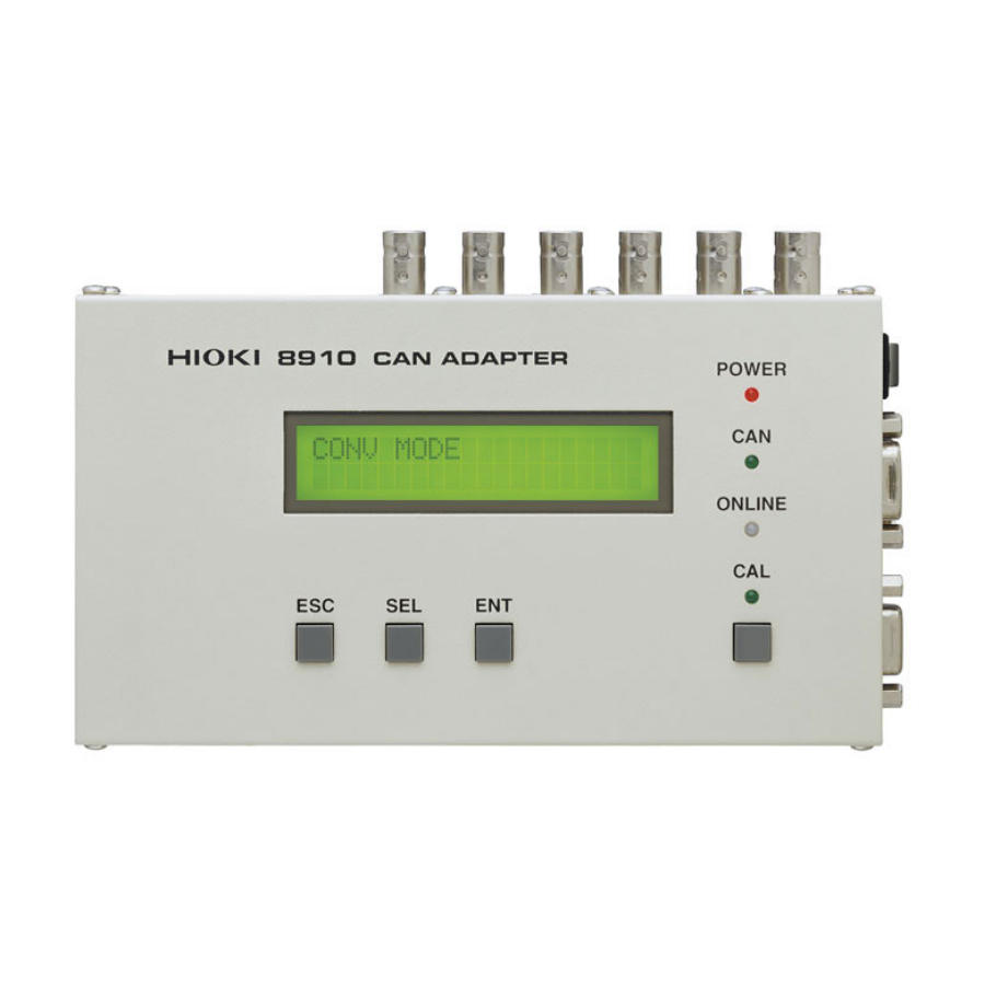
Hioki 8910 Manuals
Manuals and User Guides for Hioki 8910. We have
1
Hioki 8910 manual available for free PDF download: Instruction Manual
Hioki 8910 Instruction Manual (150 pages)
Can adapter
Brand:
Hioki
| Category:
Adapter
| Size: 2 MB
Table of Contents
Table of Contents
3
Inspection
9
Introduction
9
Safety Notes
12
Notes on Use
15
Chapter 1 Product Overview
19
Overview
19
Major Features
20
Identification of Controls and Indicators
21
Chapter 2 Preparation
23
Installation of the Instrument
23
Power Supply Connections
24
Connecting the AC Adapter
24
Connecting the DC Power Supply
25
Connection Procedure
26
Power On/Off
29
Chapter 3 Operation
31
Modes
31
Conversion Mode
31
Setting Mode
32
Activating Setting Mode
33
Contents of Display in Setting Mode
34
Selecting a Channel Number
34
Selecting the CAN Definition Data to be Output
35
Setting the D/A Conversion Format/Logic Bit Position
36
Returning to Conversion Mode
37
Calibration Mode
38
Activating Calibration Mode
38
Selecting a Channel Number
39
Outputting a Calibration Signal
39
Returning to Conversion Mode
40
Operation Map
41
Chapter 4 Preparation of the CAN Set Program
45
Overview
45
Program Setup
46
System Requirements
46
Installation
46
Un-Installation
47
Chapter 5 Starting the CAN Set Program
49
Connecting the PC to the 8910
49
Starting up the Condition Setting Program
50
Menu Items in the Setting Window
53
Operation Flowchart
54
Chapter 6 Setting the CAN Definition Data
57
Opening a CAN Definition Data File
57
Creating a New CAN Definition Data File
58
Editing the CAN Definition Data
60
Setting the Message ID
61
Setting the Data Length
61
Setting the Data Start Position
62
Setting the Data Pattern
63
Setting the Sign
64
Setting the Signal Name
65
Setting the Label Name
65
Setting the Unit
65
Setting the Scaling
66
Error Massage
68
Deletion of CAN Definition Data
69
Closing the CAN Definition Data File (Saving the File)
70
CAN Definition Data List Detail Display
71
Editing in Another Window
73
Opening a New Window
73
Creating a New CAN Definition Data File
77
Opening a CAN Definition Data File
77
Editing CAN Definition Data
77
Saving CAN Definition Data
77
Chapter 7 Settings
79
Registration List Operations
79
Opening a Registration List
79
Creating a Registration List (Registering Definition Data to a Registration List)
80
Deleting Data from the Registration List
82
Allocation to Output Channels
83
Setting Analog Output Channels
83
Deleting Registered Data from the Analog Output Allocation List
84
Setting Logic Output Channels
85
Deleting Data from the Logic Output Allocation List
86
Massage ID Trigger
87
Setting the Message ID Trigger
87
Setting Output Channels
88
Setting the ID Filter
89
Chapter 8 Transfer of Setting Data to the 8910
91
Setting Communication Parameters
91
Executing Data Transfer
92
In Case of Errors
93
Duplicate Bit Check
94
Chapter 9 Functions of the Setting Program
95
Saving the Setting Data
95
Saving Data with a New Name
95
Overwriting
96
Setting Data Printout
97
Printing
97
Print Preview
97
Setting the Printer
98
Examples of Printouts
98
Displaying Windows
100
Password Setting
101
Version Check
102
Chapter 10 Connection to Memory Hicorder
103
Using the 8910 with the 8826 MEMORY Hicorder
104
Displaying the 8910 Setting Screen
104
8910 Setting Screen
106
Setting the Block no
107
Setting Analog Channel Output
108
Setting Logic Channel Output
110
Displaying the Registration List
111
Communication between the 8826 and 8910
112
Downloading an Setting Data File
115
Using the 8910 with the 8841, 8842 MEMORY Hicorder
117
Displaying the 8910 Setting Screen
117
8910 Setting Screen
119
Setting the Block no
120
Setting Analog Channel Output
121
Setting Logic Channel Output
123
Displaying the Registration List
124
Communication between the 8841, 8842 and 8910
125
Downloading a Setting Data File
128
Chapter 11 Specifications
131
General Specifications
131
Specifications of Functions
133
Specifications of 8910 CAN Set Program (PC Application)
134
Specifications of CAN Setting Function (for Memory Hicorder)
135
Accessories
136
Options
136
9713-01 CAN CABLE (One End Unprocessed)
137
9713-02 CAN CABLE (for Automotive Connector)
138
9714-01 LOGIC CABLE (One End Unprocessed)
139
9714-02 LOGIC CABLE (for Memory Hicorder)
140
Specifications of Connectors
141
Advertisement
Advertisement
Related Products
Hioki 8860
Hioki 8861-50
Hioki 8847
Hioki 8423
Hioki 8420-51
Hioki 8421-51
Hioki 8422-51
Hioki 8731-10
Hioki MICRO HiCORDER 8206-10
Hioki 8846
Hioki Categories
Measuring Instruments
Test Equipment
Data Loggers
Multimeter
Accessories
More Hioki Manuals
Login
Sign In
OR
Sign in with Facebook
Sign in with Google
Upload manual
Upload from disk
Upload from URL