
Related Manuals for Wenglor Y1TA


Summary of Contents for Wenglor Y1TA
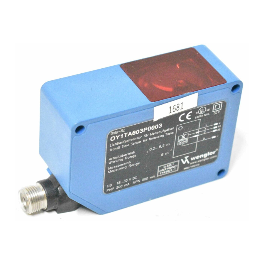
- Page 1 Y1TA OY1TA603P0003 Lichtlaufzeitsensoren Transit Time Sensors Bedienungsanleitung Operating Instructions SAP NR. 84998 Stand: 06.04.2010...
-
Page 2: Table Of Contents
6.1 Inbetriebnahme 6.2 Auslieferungszustand 7. Funktionsbeschreibung 7.1 RUN 7.2 Pin Funktion 7.3 A1/A2/A3 Schalt 7.4 A3 Fehler/A3 Eingang 7.4.1 A3 Fehler 7.4.2 A3 Eingang 7.5 A1 Analog/Analog 7.6 Offset 7.7 Messrate Sensoren für Ihren Erfolg www.wenglor.com Sensoren für Ihren Erfolg www.wenglor.com... - Page 3 7.13 Passwort 8. Weitere Einstellungen und Abfragen über die RS-232 Schnittstelle (gilt für Y1TA100QXVT80 und Y1TA100MHT88) 8.1 Fernsteuerung über ein Terminalprogramm 8.2 Fernsteuerung über Schnittstellenbefehle 9. Wartungshinweise 10. Umweltgerechte Entsorgung Sensoren für Ihren Erfolg www.wenglor.com Sensoren für Ihren Erfolg www.wenglor.com...
-
Page 4: Bestimmungsgemäße Verwendung
Vorsicht: Wenn andere als die hier angegebenen Bedienungs- oder Justiereinrichtungen benutzt oder andere Verfahrensweisen ausgeführt werden, kann dies zu gefährlicher Strahlungseinwirkung führen. CAUTION LASER RADIATION - DO NOT STARE INTO BEAM 620 - 690 nm < 1mW CLASS 2 LASER PRODUCT Sensoren für Ihren Erfolg www.wenglor.com Sensoren für Ihren Erfolg www.wenglor.com... -
Page 5: Eg-Konformitätserklärung
Folgende internationale Normen, Richtlinien und Spezifikationen sind angewendet: EN 60947-5-2:2007 Niederspannungsschaltgeräte Teil 5-2: Steuergeräte und Schaltelemente – Näherungsschalter EN 60825-1:2007 Sicherheit von Lasereinrichtungen Weitere für die Anwendung gültige Normen sind zu berücksichtigen. 50 V Sensoren für Ihren Erfolg www.wenglor.com Sensoren für Ihren Erfolg www.wenglor.com... -
Page 6: Technische Daten
50 V 50 V *Die Restwelligkeit der Versorgungsspannung darf maximal 10 % (innerhalb des angegebenen Spannungsbereiches) betragen. ** Temperaturdrift: 0,4 mm/k bei Umgebungstemperatur < –10 °C und > 50 °C Sensoren für Ihren Erfolg www.wenglor.com Sensoren für Ihren Erfolg www.wenglor.com... - Page 7 3 m auf schwarz (6 % Remission) bis 3 m auf schwarz (6 % Remission) Lichtfleckdurchmesser Arbeitsabstand 10 m Lichtfleckdurchmesser Y1TA 5 mm < 12 mm < 20 mm Abhängigkeit von Hysterese und Auflösung von der Messrate auf weiß (90 % Remission) Y1TA100 Auflösung in mm...
-
Page 8: Anschluss Der Sensoren
Be zugs masse ist hierbei Pin „–“ (Versorgungsspannung „0 V“) Anschlussleitungen M12 × 1, 8-polig Anschlussleitungen M12 × 1, 8-polig S88-10MPUR S80-2M S88-20MPUR S80-5M S88W-2MPUR S80-10M S88W-10MPUR S80W-2M S88W-20MPUR S80W-5M S80W-10M Sensoren für Ihren Erfolg www.wenglor.com Sensoren für Ihren Erfolg www.wenglor.com... -
Page 9: Gehäuseabmessungen
USB Daten – Takt weiß Eingang/Ausgang programmierbar Schnittstellen-Bus A(+)/B(-) rosa grüngelb Sendelicht abschaltbar 4.2 Gehäuseabmessungen 1 = Laser-Sendediode/Laser-Austrittsöffnung 2 = Empfangsdiode 3 = Laserwarnhinweis 4 = Typenschild inkl. Laserwarnhinweis Sensoren für Ihren Erfolg www.wenglor.com Sensoren für Ihren Erfolg www.wenglor.com... -
Page 10: Bedienfeld
Das Gerät ist so zu befestigen, dass sich die Einbaulage nicht verändern kann. Zur Montage des Sensors wird ein wenglor Befestigungssystem empfohlen. Um optimale Ergebnisse zu erzielen, sollte die Optik des Gerätes rechtwinklig zur Förderrichtung der Objekte ausgerichtet werden. -
Page 11: Inbetriebnahme
Navigation nach oben. Navigation nach unten. Auswahl des markierten Menüpunkts (Pfeil zeigt in Richtung Display). Übernahme der getroffenen Einstellung, Verlassen des Menüs (Pfeil zeigt weg vom Display). Sensoren für Ihren Erfolg www.wenglor.com Sensoren für Ihren Erfolg www.wenglor.com... -
Page 12: Auslieferungszustand
6.2 Auslieferungszustand OY1TA603P0003 Y1TA A1: Schaltausgang A1: Schaltausgang Pin Funktion A2*: Schaltausgang A3: Fehlerausgang A3: Fehlerausgang Teachmode Objekt Objekt Schaltschwelle 1000 mm 1000 mm Hysterese 20 mm 20 mm Fensterbreite 50 mm 50 mm Ausgänge PNP/NPN NO/NC Anz. Verz. 0 ms 0 ms Abf. -
Page 13: Funktionsbeschreibung
7. Funktionsbeschreibung Sensoren für Ihren Erfolg www.wenglor.com Sensoren für Ihren Erfolg www.wenglor.com... -
Page 14: Run
» Der Schaltabstand zum Objekt wird eingestellt. • Im Menüpunkt Poti bei Bedarf Einschaltpunkt Objekt Hysterese den Schaltabstand nachjustieren Ausschaltpunkt Hintergrund * Y1TA: ( ) + 10 mm z.B. Fließband Sensoren für Ihren Erfolg www.wenglor.com Sensoren für Ihren Erfolg www.wenglor.com... - Page 15 (z. B. Fließband) Hysterese • Taste T kurz drücken Ausschaltpunkt Objekt Ú Der Hintergrund wird ausgeblendet Hintergrund * Y1TA: ( ) + 10 mm z.B. Fließband T Fenster Teachen eines Toleranzfensters Durch Drücken der Taste T wird ein Toleranzfenster eingeteacht: •...
- Page 16 Taste + bzw. – wird eine Impulslänge von 0 ms bis 10000 ms eingestellt. Anzugszeitverzögerung Nach der eingestellten Impulszeit geht das Ausgangssignal Impulslänge in den Zustand nicht geschaltet zurück. Funktion kann mit Anzugszeit- verzögerung kombiniert werden. Sensoren für Ihren Erfolg www.wenglor.com Sensoren für Ihren Erfolg www.wenglor.com...
-
Page 17: A3 Fehler/A3 Eingang
Verwendung als invertierter Eingang Der Eingang liegt im Normalfall auf einer Spannung > 7 V. Die Funktionalität des Eingangs des Eingangs wird bei Anlegen einer Spannung < 7 V ausgelöst. Sensoren für Ihren Erfolg www.wenglor.com Sensoren für Ihren Erfolg www.wenglor.com... -
Page 18: A1 Analog/Analog
10 V Abstand bei 10 V – Durch Drücken der Taste + bzw. – wird der dem Wert 10 V bzw. 20 mA zugeordneten Abstand nachjustiert werden. Sensoren für Ihren Erfolg www.wenglor.com Sensoren für Ihren Erfolg www.wenglor.com... -
Page 19: Offset
Um den Offset-Abgleich anzuwenden, ist am Eingangspin eine Spannung > 7 V anzulegen, um eine positive Flanke auszulösen. Dabei wird der im Menüpunkt Vorgabe eingestellte Wert als aktueller Abstand übernom- men. Sensoren für Ihren Erfolg www.wenglor.com Sensoren für Ihren Erfolg www.wenglor.com... - Page 20 Der Schaltabstand verschiebt sich somit um 4000 mm auf reale 9000 mm. Anwenden des Offset-Abgleichs 3000 mm eingestellter Schaltabstand: 7000 mm 3000 mm 4000 mm 5000 mm 9000 mm [Abstand mit Meterma gemessen(mm)] Sensoren für Ihren Erfolg www.wenglor.com Sensoren für Ihren Erfolg www.wenglor.com...
-
Page 21: Messrate
Ist Pin 5 schon als RS-232 Schnittstelle belegt, kann die Laserdiode über Schnitt stellenbefehl, im Menü oder über A3 Eingang (s. 6.2 Pin Funktion/6.4.2 A3 Eingang) ausgeschaltet werden. Bei Y1TA100MHV80 ist die Laserdiode über Pin 8 abschaltbar, indem Pin 8 an 24 V gelegt wird. Sensoren für Ihren Erfolg www.wenglor.com Sensoren für Ihren Erfolg www.wenglor.com... -
Page 22: Anzeige
Analog: Im Display wird der Analogausgangswert angezeigt. Ausgangskonfiguration/ eingestellte Verzögerung Analogausgangswert (U/I) Gemessene Abstand zum Analogspannung Objekt Wechsel zur Anzeigeansicht Durch Drücken der Taste wird in den Anzeigemodus gewechselt. Sensoren für Ihren Erfolg www.wenglor.com Sensoren für Ihren Erfolg www.wenglor.com... -
Page 23: Schnittstelle (Gilt Für Y1Ta100Qxvt80 Und Y1Ta100Mht88)
Durch Drücken der Tasten bzw. wird zwischen den beiden Ausgabeformaten ASCII und Binär (Standar- deinstellung) ausgewählt. TA/T Einstellen des Schnittstellenprotokolls Durch Drücken der Tasten bzw. kann vom neuen Schnittstellenprotokoll (Y1TA) auf das bisherige Schnittstellenprotokoll (YT) gewechselt werden. Intervall Einstellen des Sendeintervalls beim Dauer-Senden – [Daten] Die Länge des Intervalls definiert, in welchen Abständen... - Page 24 Die einzelnen Werte werden hintereinander in einer Zeile ausgegeben. Es werden nur die Werte der ausge- wählten Spalten ausgegeben. Sensoren für Ihren Erfolg www.wenglor.com Sensoren für Ihren Erfolg www.wenglor.com...
- Page 25 00000000 2068 mm Durch die Ausgabe des Zeitstempels können die einzelnen Messabstände ohne Berücksichtigung der Verar- beitungsgeschwindigkeit des Rechners einer relativen Zeit zugeordnet werden. Zeitstempel: D 1 ≙ 500 µs Sensoren für Ihren Erfolg www.wenglor.com Sensoren für Ihren Erfolg www.wenglor.com...
-
Page 26: Display
Im Menü Reset können die Sensoreinstellungen in den Auslieferungszustand zurückgesetzt werden. Auslieferungszustand der Einstellungen siehe Kapitel 8. Bezeichnung Funktion Tastenbelegung Reset Druecke <R> fuer Reset Durch Drücken der Taste R werden die getroffenen Sensoreinstellungen in den Auslieferungszustand zurück- gesetzt. Sensoren für Ihren Erfolg www.wenglor.com Sensoren für Ihren Erfolg www.wenglor.com... -
Page 27: Passwort
Mit dieser Funktion kann der Sensor ohne Stromunterbrechung gesperrt werden. Durch Drücken der Taste sperren Sie den Sensor und gelangen direkt in den Passwort-Eingabe Modus. Hier ist eine Passwort-Eingabe erforderlich, um den Sensor weiter bedienen zu können. Sensoren für Ihren Erfolg www.wenglor.com Sensoren für Ihren Erfolg www.wenglor.com... -
Page 28: Weitere Einstellungen Und Abfragen Über Die Rs-232 Schnittstelle
Es ist sicherzustellen, dass der neu festgelegte Code notiert wird, bevor die Passwort-Änderung erfolgt. Ein vergessenes Passwort kann nur durch einen General-Passwort überschrieben werden. Das General-Passwort kann per E-Mail bei support@wenglor.com angefordert werden. 8. Weitere Einstellungen und Abfragen über die RS-232 Schnittstelle (gilt für Y1TA100QXVT80 und Y1TA100MHT88) -
Page 29: Fernsteuerung Über Ein Terminalprogramm
Sensor über die wenglor-Steckerweiche S232W3 mit PC, Steuerung etc. verbinden: Installieren der Steckerweiche wie folgt: • 8-poliges Anschlusskabel (S80-xx/S88-xx) vom Sensor trennen • Steckerweiche S232W3 direkt am Sensor einstecken • 8-poliges Anschlusskabel (S80-xx/S88-xx) an der Steckerweiche einstecken • 9-poligen SUB-D-Stecker am PC an der seriellen Schnittstelle anschließen •... -
Page 30: Fernsteuerung Über Schnittstellenbefehle
• Verwenden Sie zur Reinigung des Sensors keine Lösungsmittel oder Reiniger, die das Gerät beschädigen könnten. 10. Umweltgerechte Entsorgung Die wenglor sensoric gmbh nimmt unbrauchbare oder irreparable Produkte nicht zurück. Bei der Entsorgung der Produkte gelten die jeweils gültigen länderspezifischen Vorschriften zur Abfallentsorgung. Sensoren für Ihren Erfolg www.wenglor.com... - Page 31 Sensoren für Ihren Erfolg www.wenglor.com Sensoren für Ihren Erfolg www.wenglor.com...
- Page 32 6.2 Default Settings 7. Functional Overview 7.1 RUN 7.2 Pin Function 7.3 A1/A2/A3 Switch 7.4 A3 Error/A3 Input 7.4.1 A3 Error 7.4.2 A3 Input 7.5 A1 Analog/Analog 7.6 Offset 7.7 Sampling Rate Sensors for your success www.wenglor.com Sensors for your success www.wenglor.com...
- Page 33 8. More Settings and Queries via the RS-232 Interface (does apply to Y1TA100QXVT80 and Y1TA100MHT88) 8.1 Remote Control via a Terminal Program 8.2 Remote Control with Interface Commands 9. Maintenance Instructions 10. Proper Disposal Sensors for your success www.wenglor.com Sensors for your success www.wenglor.com...
-
Page 34: Use For Intended Purpose
Caution: Use of controls, adjustments or performance of procedures other than those specified herein may result in hazardous radiation exposure CAUTION LASER RADIATION - DO NOT STARE INTO BEAM 620 - 690 nm < 1mW CLASS 2 LASER PRODUCT Sensors for your success www.wenglor.com Sensors for your success www.wenglor.com... -
Page 35: Ec Declaration Of Conformity
Part 5-2: Control circuit devices and switching elements – proximity switches EN 60825-1: 2007 Safety of laser devices Any additional standards which are applicable for the given application must be observed. 50 V wenglor offers Connection Technology providing field wiring means. Sensors for your success www.wenglor.com Sensors for your success... -
Page 36: Device Features
50 V *Supply voltage residual ripple may not exceed 10 % (within the specified voltage range). **Temperature Drift: 0,4 mm/k at ambient temperature < –10 °C and > 50 °C Sensors for your success www.wenglor.com Sensors for your success www.wenglor.com... - Page 37 Up to 3 m on black (6 % remission) Light Spot Diameter Working Distance 10 m Light Spot Diameter Y1TA 5 mm < 12 mm < 20 mm Dependence of Hysteresis and Resolution on the Sampling Rate on white (90 % Remission)
-
Page 38: Connecting The Sensors
In the case of Y1TA100QXT3 and Y1TA100QXVT80, Pin ”A1“ can also be used as an analog output. The reference to ground here is Pin “–“ (supply voltage “0 V“) Connecting Cables M12 × 1, 8-pin Connecting Cables M12 × 1, 8-pin S88-10MPUR S88-20MPUR S88W-2MPUR S88W-10MPUR S88W-20MPUR Sensors for your success www.wenglor.com Sensors for your success www.wenglor.com... -
Page 39: Housing Dimensions
Green Yellow Emitted Light disengageable 4.2 Housing Dimensions 1 = Laser Diode/Laser Aperture 2 = Receiver Diode 3 = Laser Warning Sign 4 = Name Plate incl. Laser Warning Sign Sensors for your success www.wenglor.com Sensors for your success www.wenglor.com... -
Page 40: The Control Panel
The sensor must be protected against mechanical influences. Install the device such that its installation position cannot be inadvertently changed. The wenglor mounting system is recommended for installing the sensor. In order to obtain best possible results, the device’s optics should be aligned at a right angle to the direction in which the objects are conveyed. -
Page 41: Initial Start-Up
Navigation up. Navigation down. Acknowledge the selected menu item (arrow points towards the display). Accept the selected setting, exit the menu (arrow points away from the display). Sensors for your success www.wenglor.com Sensors for your success www.wenglor.com... -
Page 42: Default Settings
6.2 Default Settings OY1TA603P0003 Y1TA A1: Switching output A1: Switching output Pin Function A2*: Switching output A3: Error output A3: Error output Teach Mode Object Object Switching threshold 1000 mm 1000 mm Hysteresis 20 mm 20 mm Window Size 50 mm... -
Page 43: Functional Overview
Baudrate ASCII 11. Interface TA/T Interval Mask Mirror 12. Display Intensity Deutsch English 13. Language Francais Sensor type 14. Info Sensor version 15. Reset Enable Enter 16. Password Change Lock Sensors for your success www.wenglor.com Sensors for your success www.wenglor.com... -
Page 44: Run
• If necessary, readjust the Making point Object switching distance with the help Hysteresis of the Potentiometer menu item. Breaking point Background * Y1TA: ( ) + 10 mm e.g. conveyor belt Sensors for your success www.wenglor.com Sensors for your success www.wenglor.com... - Page 45 • Briefly press the T key. Breaking point Object Ú The background is suppressed. Background * Y1TA: ( ) + 10 mm e.g. conveyor belt T Window Teach-In a tolerance window A window tolerance is taught in by pressing the T key: •...
- Page 46 + or the – key. After the selected impulse duration has elapsed, the output signal is returned Impulse duration to the deactivated state.. Function can be combined with ON-delay. Sensors for your success www.wenglor.com Sensors for your success www.wenglor.com...
-
Page 47: A3 Error/A3 Input
Usage as inverted input The input is normally at a voltage of > 7 V. The functionality of the input is triggered upon applying a voltage < 7 V. Sensors for your success www.wenglor.com Sensors for your success www.wenglor.com... -
Page 48: A1 Analog/Analog
The distance assigned to either 0 V or 4 mA is adjusted by pressing the + or the – key. at 10 V Distance at 10 V – The distance assigned to either 10 V or 20 mA is adjusted by pressing the + or the – key. Sensors for your success www.wenglor.com Sensors for your success www.wenglor.com... -
Page 49: Offset
In order to apply the Offset equalization, a voltage > 7 V should be applied at the input pin to trigger a positive flank. Here, the value set in the menu option Preset is accepted as the current distance. Sensors for your success www.wenglor.com Sensors for your success www.wenglor.com... - Page 50 The switching distance thus gets displaced by 4000 mm to the actual 9000 mm. Application of the offset equalization 3000 mm Switching distance set: 7000 mm 3000 mm 4000 mm 5000 mm 9000 mm [Distance measured with a meter ruler (mm)] Sensors for your success www.wenglor.com Sensors for your success www.wenglor.com...
-
Page 51: Sampling Rate
A3 input (see 6.2 Pin Function/6.4.2 A3 input). In case of the Y1TA100MHV80 the laser diode can be switched off via pin 8, by connecting pin 8 to 24 V. Sensors for your success www.wenglor.com Sensors for your success www.wenglor.com... -
Page 52: Read-Out
Analog output value (U/I) Measured analog Distance to the voltage object Switch to the read-out view The device is switched to the display mode by pressing the key. Sensors for your success www.wenglor.com Sensors for your success www.wenglor.com... -
Page 53: Interface (Does Apply To Y1Ta100Qxvt80 And Y1Ta100Mht88)
Selection of the interface protocol Switching between the old and new interface protocols (Y1TA and YT respectively) is possible by pressing the or the key. Interval Selection of the transmission interval for continuous transmission ... - Page 54 The individual values are read out consecutively to a single line. Only the values for the selected columns are read out. Sensors for your success www.wenglor.com Sensors for your success www.wenglor.com...
- Page 55 By outputting the time-stamp, the individual measurement distances can be assigned to a relative time without taking into consideration the processing speed of the computer. Time stamp: D 1 ≙ 500 µs Sensors for your success www.wenglor.com Sensors for your success www.wenglor.com...
-
Page 56: Display
8. Designation Function Key designation Reset Press <R> to reset All of the selected sensor settings are returned to their default values by pressing the R key. Sensors for your success www.wenglor.com Sensors for your success www.wenglor.com... -
Page 57: Password
The sensor is disabled and switched automatically to the password entry mode after pressing the key. A password must be entered in order to continue using the sensor. Sensors for your success www.wenglor.com Sensors for your success www.wenglor.com... -
Page 58: More Settings And Queries Via The Rs-232 Interface
Interface configuration: Adjustable baud rate, 8 data bits, no parity, 1 stop bit Plug connectors included with the wenglor S232W3 plug adapter: • 8-pin M12 plug connector for connecting the power supply and the outputs • 8-pin M12 socket connector for direct sensor connection •... -
Page 59: Remote Control Via A Terminal Program
Connect the sensor to the PC, the controller etc. via the wenglor S232W3 plug adapter. Install the plug adapter as follows: • Disconnect the 8-conductor connector cable (S80-xx) from the sensor. • Connect the S232W3 plug adapter directly to the sensor. -
Page 60: Remote Control With Interface Commands
• Select <Mode>. • Select <Comm>. The sensor is now ready for interface communication. The interface protocol for the Y1TA can be downloaded as a PDF document from our website at www.wenglor.com under the “download” heading. 9. Maintenance Instructions • This wenglor sensor is maintenance-free. - Page 61 Sensors for your success www.wenglor.com Sensors for your success www.wenglor.com...
- Page 62 Sensors for your success www.wenglor.com Sensors for your success www.wenglor.com...
- Page 63 Sensors for your success www.wenglor.com Sensors for your success www.wenglor.com...
- Page 64 ( + 421 48 414 70 86/87 steletronic@steletronic.com.br info.hu@wenglor.com eximtech@eximtech.sk Bulgaria – Sofia India – Mahape, Navi Mumbai Slovenia/Croatia/Serbia wenglor sensoric romania srl wenglor sensoric india private limited SENSOR d.o.o. ( +40 (0)269 2077-00 ( +91 (022) 4158 0100 ( +386 2 613-1831 info.ro@wenglor.com info.in@wenglor.com sensor@siol.net Canada –...
Need help?
Do you have a question about the Y1TA and is the answer not in the manual?
Questions and answers