
Related Manuals for Wenglor SG4-I


Summary of Contents for Wenglor SG4-I
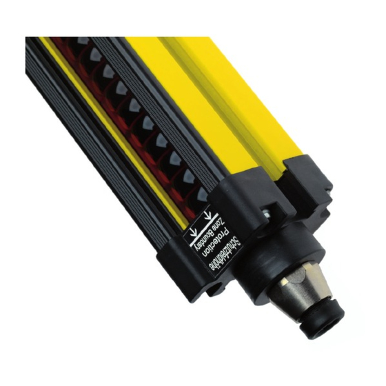
- Page 1 SG4-I Safety Light Curtain Operating instructions Available as PDF only Status: 17.10.2017 Version: 12 www.wenglor.com...
-
Page 2: Table Of Contents
Table of Contents 1. General 1.1 Function and Use for Intended Purpose 1.2 Features 1.3 Applications Examples 1.3.1 Single Curtain Protection 1.3.2 Cascading Two Light Curtains 1.3.3 Use at Brake Presses 1.4 Brief Explanation of Function- and Operating Modes 1.5 Explanation of symbols 2. - Page 3 5.5 Cascading (Linking Several Light Curtains) 5.5.1 Principle 5.5.2 Cascading Procedure 5.5.3 Functions 5.5.4 Coding 6. Expanding the Light Curtain System 6.1 Relay Unit 6.2 Muting Module 6.3 Connection to a PC 6.4 Path-Folding Mirror 7. Display 7.1 Display of Operating Modes 7.2 Diagnostic information 8.
-
Page 4: General
1. General The SG4 light curtain system is a design-approved, electro-sensitive protection equipment (ESPE) in accordance with EN 61496-1. It’s a class 4 Light Curtain, i.e. it’s an ESPE for which the safety function remains intact even if several errors occur. Furthermore, it’s a category 4 Safety Light Curtain, and is thus a self-testing safety device. The light curtain system consists of a emitter module and a receiver module. -
Page 5: Single Curtain Protection
1.3.1 Single Curtain Protection Example: securing an area 1.3.2 Cascading Two Light Curtains Example: securing off an area plus side-stepping protection 1.3.3 Use at Brake Presses Example: floating blanking... -
Page 6: Brief Explanation Of Function- And Operating Modes
1.4 Brief Explanation of Function- and Operating Modes Auto Floating Blanking This operating mode is the same as Floating Blanking, except that in this case the object (for example a skid carrier or lifting forks) moves through and exits the safety field. The direction at which the object enters and exits the safety field, as well as its dwell time within the safety field, must be defined. -
Page 7: Explanation Of Symbols
1.5 Explanation of symbols Points up suggestion and tips, which simplify the handling of the safety light curtain. Points at a measure to prevent a concrete danger. Points at functions, which can only be configured by means of software (PC). 2. -
Page 8: Important Notes Concerning Use
All specified data make reference to the following revision level: 17.10.2017 Technical changes to the product described herein, printing errors and/or any possible incompleteness of this prod- uct description may not be construed as cause for asserting any legal claims whatsoever against wenglor sensoric GmbH. -
Page 9: Securing The Danger Zone
3.2 Securing the Danger Zone The danger zone must be secured by means of the light curtain alone, or by means of the light curtain in combination with additional mechanical safety devices. Reaching around, over and/or under the safety field must be prevented in any case. It must be impossible to approach the point of danger without passing through the safety field. -
Page 10: Calculating Safety Clearance Per En Iso 13855
3.3 Calculating Safety Clearance per EN ISO 13855 Calculation of safety clearance S is based upon the EN ISO 13855 standard. However, if any special directives and standards apply to the respective machine, these must be taken into consideration as well. Each contactless safety device must be mounted such that stepping or reaching into the danger zone is precluded. -
Page 11: Direction Of Approach To The Safety Field
Approach/Reach-In Speed Constant K Amongst other factors, safety clearance depends upon the maximum reach-in or walking speed of the person pen- etrating the safety field. Safety Margin C Safety margin C depends upon the respective resolution of the light curtain.. 3.3.1 Direction of Approach to the Safety Field 3.3.1.1 Perpendicular Approach to the Safety Field The following equations apply:... -
Page 12: Sample Calculations
3.3.2 Sample Calculations Example 1: Light curtain with a safety field height of 764 mm, vertical installation, 14 mm resolution Assuming: light curtain response time SG4-14Ix075C1 t1 = 26 ms machine over-travel time t2 = 20 ms light curtain resolution d = 14 mm approach speed K = 2000 mm or 1600 mm/s... -
Page 13: Minimum Clearance To Reflective Surfaces
3.4 Minimum Clearance to Reflective Surfaces If reflective surfaces are located within the aperture angle between the emitter and the receiver, reflection may result which could cause an obstruction to go undetected. For this reason, a minimum clearance m between reflective objects and the optical axis must be maintained. Beam angles are taken from the IEC 61496-2 standard. -
Page 14: Connection And Installation To The Machine
It is advisable to mount the light cur- tain for initial start-up such that alignment can still be adjusted to an adequate extent. wenglor offers acces- sories which allow for easy adjustment. The controls must be accessible for initial start-up and maintenance. These are located on the side from which the beam is emitted (emitter), or the side at which the beam is received (receiver). - Page 15 Basic Schematic Diagram Receiver Control Panel Safety PLC (Cat. 4; PL e; SIL3) Socket Display 2 Display 1 or Safety-Relay Blanking Alignment (YE) Failure (RD) Contactor Monitor OSSD off (RD) OSSD on (GN) Plug Receiver Acknowledge OSSD 2 Enter Button OSSD 1 Dip Switch S1 24 V...
-
Page 16: Default Settings
Receiver Wiring Pin 1 Signal output free Pin 2 24 V DC Supply Voltage 24 V DC Pin 3 OSSD1 output PLC or relay Pin 4 Acknowledge free Pin 5 Contactor monitor free Pin 6 OSSD 2 output PLC or relay Pin 7 Ground (0 V) Supply Voltage 0 V... -
Page 17: Operating The Light Curtain
5. Operating the Light Curtain Receiver Emitter 5.1 Pilot Beam The pilot beam is used to synchronise the light curtain. It is the closest beam to the display and may not be continuously interrupted. Pilot Beam 5.2 Adjustment The purpose of adjustment is to accurately set the light curtain receiver to the required range. Adjustment must be performed after mechanical installation of the light curtain. -
Page 18: Adjustment Procedure
5.2.2 Adjustment Procedure DIP Switch Settings: Receiver Start Serial Communication Timing Set all DIP Cascading switches to off Reduced Resolution Align the light curtain mechanically Fix Blanking Contactor Monitoring Press and hold the enter button on the Restart Inhibit receiver for 1 s Improve alignment Do the... -
Page 19: Function Modes
5.3 Function Modes The Light Curtain can be used with four different function types: • Safety operating mode • Start-Up inhibit and restart inhibit • Contactor monitoring These functions, and how to set them up at the Light Curtain, are explained in detail below. The Start-Up inhibit and restart inhibit function types are treated as a single topic based upon the same setup procedure. - Page 20 Schematic Diagram, Restart Inhibit Receiver Control Panel Socket Display 2 Display 1 Safety PLC (Cat. 4; PL e; SIL3) or Safety Relay Blanking Failure (RD) Alignment (YE) Contactor Monitor OSSD off (RD) OSSD on (GN) Plug Receiver Acknowledge OSSD 2 Enter Button Acknowledge OSSD 1...
-
Page 21: Contactor Monitoring
Receiver Wiring Pin 1 Signal output free Pin 2 24 V DC Supply Voltage 24 V DC Pin 3 OSSD 1 Output PLC or relay Pin 4 Acknowledge Pushbutton (normally open) 24 V DC Pin 5 Contactor monitor free Pin 6 OSSD 2 Output PLC or relay Pin 7... - Page 22 Schematic Diagram, Contactor Monitoring Receiver Control Panel Load Load Load Load Circuit A Circuit B Circuit A Circuit B Socket Load Load Load Load Display 2 Display 1 Circuit A Circuit B Circuit B Circuit A Contacor Monitor Blanking Failure (RD) Alignment (YE) OSSD off (RD) OSSD on (GN)
-
Page 23: Blanking Options
Receiver Wiring Pin 1 Signal Output free Pin 2 24 V DC Supply Voltage 24 V DC Pin 3 OSSD 1 Output PLC or relay Pin 4 Acknowledge free Pin 5 Contactor monitor 24 V via contactor (NC contact) Pin 6 OSSD 2 Output PLC or relay Pin 7... -
Page 24: Principle
5.4.1.1 Principle A fixed object is always located at the same position within the safety field. The beams which are obstructed by this object can be blanked. There is a limit to the number of beams which can be blanked (see table 1 on page 36). - Page 25 Schematic Diagram, Fix Blanking Receiver Control Panel Safety PLC (Cat. 4; PL e; SIL3) Socket or Safety Relay Display 2 Display 1 Contactor Monitor Blanking Failure (RD) Alignment (YE) Plug Receiver OSSD off (RD) OSSD on (GN) Acknowledge OSSD 2 Enter Button OSSD 1 24 V...
-
Page 26: Fix Blanking Procedure
Receiver Wiring Pin 1 Signal output Unused Pin 2 24 V DC Supply Voltage 24 V DC Pin 3 OSSD 1 output PLC or relay Pin 4 Acknowledge free Pin 5 Contactor monitor free Pin 6 OSSD 2 output PLC or relay Pin 7 Ground (0 V) Supply Voltage 0 V... -
Page 27: Calculating Safety Clearance
5.4.1.3 Calculating Safety Clearance Safety clearance is calculated with the same method used for a non-blanked safety light curtain. Mechanical curtains must be utilized in order to assure that fix blanked beams cannot be penetrated. 5.4.2 Floating Blanking In certain applications, objects protrude continuously into the safety field, although their positions cannot be precisely pinpointed. - Page 28 Schematic Diagram, Floating Blanking Receiver Control Panel Safety PLC (Cat. 4; PL e; SIL3) Socket or Safety Relay Display 2 Display 1 Blanking Failure (RD) Contactor Monitor Alignment (YE) OSSD off (RD) OSSD on (GN) Plug Receiver OSSD 2 Acknowledge Enter Button OSSD 1 Dip Switch S1...
-
Page 29: Floating Blanking Procedure
The parameters for this function type can only be configured via the serial port. Connection to a PC is described in section 6.3. The required wsafe software can be downloaded along with instructions from the wenglor website. 5.4.2.3 Calculating Safety Clearance Whether or not penetration into the exclusion area is possible plays a significant role in calculating safety clearance. - Page 30 Example 2: Number of beams obstructed by the object: 3 Max. number of floating beams Difference: If penetration into the exclusion zone is not possible, light curtain resolution remains unchanged. The maximum number of floating beams is otherwise used to determine resolution. Table: Resulting Resolution with Floating Blanking and Auto-Floating Blanking Max.
- Page 31 sample calculation:: SG4-30Ix030C1 Assuming: Light Curtain response time = 5,7 ms Machine over-travel time = 20 ms Approach speed K = 2000 ms 1 obstructed beam d = 47 mm Because resolution is greater than 40 mm C = 850 mm (see safety clearance calculation in section 3.3, „Calculating Safety Clearance per EN ISO 13855“) Due to the fact that a safety clearance of 500 mm results alone from C, we only need to use K = 1600 mm/s for our calculation.
-
Page 32: Auto Floating Blanking
5.4.3 Auto Floating Blanking This operating mode is required for applications with moving objects which continuously move through and exit the safety field (e.g. skid carriers and forklifts), thus interrupting specific light curtain beams in a defined fashion. Intrusions into any other point within the safety field cause the safety output to switch and stop haz- ardous motion. -
Page 33: Auto Floating Blanking Procedure
Prerequisites for use: • Only those objects which actually protrude into or pass through the safety field during operation may be used for the configuration. • Testing must be performed in order to determine whether or not floating blanking can be used, whereby all possible object arrangements (practical experience) have to be tested. -
Page 34: Calculating Safety Clearance
Connector Pin Assignments for Safety Operation with Auto-Floating Blanking Required system components: 1 × emitter, 1 × receiver 1 × connector cable for emitter 1 × connector cable for receiver 1 × Mutingmelder From Emitter Wiring Pin 1 24 V DC Supply Voltage 24 V DC Pin 2 Unused... -
Page 35: Reduced Resolution
5.4.4 Reduced Resolution Light curtain resolution can be reduced with the help of the reduced resolution function. As opposed to light curtains with mechanically reduced resolution, electronically reduced resolution provides for significantly greater functional reserves. This is due to the fact that objects which are smaller than the selected resolution do not cause the safety output to switch where electronically reduced resolution is utilized. - Page 36 Schematic Diagram, Reduced Resolution Receiver Control Panel Safety PLC (Cat. 4; PL e; SIL3) Socket or Safety Relay Display 2 Display 1 Contactor Monitor Blanking Failure (RD) Alignment (YE) Plug Receiver OSSD off (RD) OSSD on (GN) OSSD 2 Acknowledge Enter Button OSSD 1 24 V...
-
Page 37: Reduced Resolution Procedure
Receiver Wiring Pin 1 Signal output Muting indicator muting terminal Pin 2 24 V DC Supply Voltage 24 V DC Pin 3 OSSD 1 output PLC or relay Pin 4 Acknowledge free Pin 5 Contactor monitor free Pin 6 OSSD 2 output PLC or relay Pin 7 Ground (0 V) -
Page 38: Calculating Safety Clearance
5.4.4.3 Calculating Safety Clearance Light curtain resolution is identical to electronically reduced resolution in the “reduced resolution” operating mode (see table). Table: Reduced Resolution • Finger protection: max. reduced resolution = 105 mm • Hand protection: max. reduced resolution = 98 mm Resolution d for Resolution d for Number of... -
Page 39: Summary Of Blanking Options
5.4.5 Summary of Blanking Options Fix Blanking Floating Blanking Auto Floating Reduced Blanking Resolution Only within the Inside and outside of Inside and out- Object moves safety field the safety field side of the safety field Removal Causes switching of Causes switching of the Does not cause Does not cause... -
Page 40: Principle
5.5.1 Principle • By interconnecting several receivers, they can be linked such that they all act upon a single safety output. • Response time is increased by 1 ms per additional receiver. • It is not advisable to cascade more than 5 devices. •... - Page 41 Schematic Diagram, Cascading Receiver 1 Safety PLC Socket (Cat. 4; PL e; SIL3) or Safety Relay Contactor Monitor Serial Communication Timing Cascading Plug Receiver 1 Reduced Resolution Acknowledge OSSD 2 OSSD 1 Fix Blanking 24 V Signal output Contactor Monitoring Restart Inhibit Earth/shield 8) Serial Communication...
-
Page 42: Functions
5.5.3 Functions Receiver 1 Receiver 2 Effect on common output Restart inhibit Activated Must be acknowledged after penetration into safety field 1/2. Activated Must be acknowledged after penetration into safety field 2. Activated Activated not reasonable, because an interference of safety field 2 has to be acknowledged twice. -
Page 43: Coding
5.5.4 Coding wenglor light curtains are coded at the factory in order to assure that any given emitter is only capable of influenc- ing its own corresponding receiver. The coding of the light curtain can be changed during initial start-up. Coding is... -
Page 44: Expanding The Light Curtain System
6. Expanding the Light Curtain System 6.1 Relay Unit The SG4-00VA000R2 relay unit is equipped with two failsafe floating relay outputs. The terminals are con- nected to the load circuit. The use of a spark arrestor significantly increases the service life of the relay contact. -
Page 45: Muting Module
Relay Unit Terminal Assignments Required system components: 1 × emitter, 1 × receiver 1 × cable 1 × connector cable 1 × relay unit From Function Relay Unit Connections Terminal 1 NO, 13 Machine contact Terminal 2 NO, 23 Machine contact Terminal 3 NO, 24 Machine contact... -
Page 46: Connection To A Pc
PC. In order to activate the interface, the “serial communication” DIP switch must be set to the “on” position. wsafe host software allows for configuration and read-out of the light curtain. Operating instructions for the host software can be downloaded from the wenglor website at www.wenglor.com. That encloses: •... -
Page 47: Path-Folding Mirror
With safety column: SZ000EUxxxNN01 Danger Zone A danger zone can be secured at several sides using only one light curtain with the help of a wenglor path-folding mirror. Range is reduced by approximately 10 % per uti- lized mirror. Receiver For an easier adjustment the special alignment optic SZ0- LAH01 can be used. -
Page 48: Display
7. Display 7.1 Display of Operating Modes During normal operation, operating modes and functions appear at the receiver’s display. If any errors should occur, the error LED lights up and a corresponding error code is displayed. Additional information is read out at the setup LED. -
Page 49: Diagnostic Information
7.2 Diagnostic information Diagnostic Code Cause Remedy FF** No synchronisation, pilot beam is obstruct- Free up the pilot beam or readjust the light curtain. 15, 45 Leakage of data in safety light curtain. Encode anew, if necessary contact technical support. 18, 48, 17, 47 Influence through ambient light, other sen- Remove receiver from the cone of... -
Page 50: Condensed Start-Up Instructions
8. Condensed Start-Up Instructions Start Set all DIP switches to off Align the light curtain mechanically Press and hold the enter button on the receiver for 1 s Improve alignment Do the blanking alignment and failure LEDs blink? 99 – very good see table “Degree of alignment Alignment degree against the distance between... -
Page 51: Inspection Prior To Initial Start-Up
9.1 Inspection Prior to Initial Start-Up Inspection prior to initial start-up, conducted by trained personnel, is intended to assure that the electro-sensitive protective equipment (ESPE), as well as any other safety components, have been correctly selected in accordance with local ordinances, and that they provide the required protection when used for their intended purpose. •... -
Page 52: Environmentally Sound Disposal
The light curtains’ housings are made of aluminium, and can be disposed of at an ap- propriate recycling centre. All electronic components must be disposed of as special waste. wenglor sensoric gmbh does not accept the return of unusable or irreparable devices. -
Page 53: Hand Protection Emitter
11.3 Hand Protection Emitter Overall Length Hand protec- in mm tion Safety Field (dimension G) Height in mm (SFHH) SG4-30IS015C1 298,1 180,2 SG4-30IS030C1 448,3 330,4 SG4-30IS045C1 598,5 480,6 SG4-30IS060C1 748,7 630,8 SG4-30IS075C1 898,9 781,0 SG4-30IS090C1 1049,1 931,2 SG4-30IS105C1 1199,3 1081,4 SG4-30IS120C1 1349,5 1231,6... -
Page 54: Mounting Bracket Bef-Set-33
11.5 Mounting Bracket BEF-SET-33 12. Technical Data 12.1 Safety Light Curtains Type Type 4 per EN 61496 Safety category Cat. 4 per EN ISO 13849-1 Performance Level PL e per EN ISO 13849-1 PFHd SG4-14: 4,22 × 10⁻⁸ 1/h SG4-30: 3,08 × 10⁻⁸ 1/h Service life TM 20 a Resolution... - Page 55 Supply power, receiver 24 V DC ±10 % 6 W; PELV per EN 50178 Supply power, emitter 24 V DC ±10 % 6 W; PELV per EN 50178 Fuse 1,5 A Outputs Safety outputs 2 ea. semiconductor, PNP Output current with ohmic, inductive load 2 ea.
-
Page 56: System Components
12.2 System Components 12.2.1 Relay Unit Type 2/Type 4 SG4-00VA000R2 Output 2 sets of 2 NO contacts Response time 8 ms Contact load Max. switching capacity 1500 VA/AC Voltage/Current/ Switching Cycles B10 250 V AC / 4 A / 180 000 24 V DC / 4 A / 1 400 000 24 V DC / 2 A / 3 000 000 Mechanical Service Life... -
Page 57: Connection Line
12.2.5 Connection Line M12 × 1, 4-pin Length Angle Plug Straight Plug S29-2M — S23-2M S23-2MPUR S29-5M S29-5MPUR S23-5M S23-5MPUR 10 m S29-10M — S23-10M S23-10MPUR M12 × 1, 8-pin Length Straight Plug Angle Plug Straight Plug Angle Plug S88-2MPUR S88W-2MPUR ZAS89R201 ZAS89R202... -
Page 58: Checklist For Initial Start-Up
13. Checklist for Initial Start-Up This checklist is intended to provide assistance during initial start-up. It does not eliminate the need for testing before initial start-up, or for periodic tests conducted by appropriately trained persons. 1. Standards and Directives, ESPE Selection Are the safety precautions based upon the directives/standards which are applicable for the machine? Are the utilized directives and standards listed in the declaration of conformity? -
Page 59: Eu Declaration Of Conformity
15. EU Declaration of Conformity Subject to change without notice. Translation of the Original Operating Instruction.
Need help?
Do you have a question about the SG4-I and is the answer not in the manual?
Questions and answers