Table of Contents
Advertisement
Quick Links
Advertisement
Table of Contents

Related Manuals for Wenglor OPT2139

Summary of Contents for Wenglor OPT2139
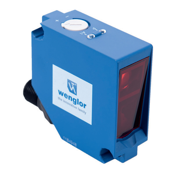
- Page 1 OPT2139 OPT2140 Retro-Reflex Sensors for Clear Glass Recognition Operating Instructions Translation of the Original Operating Instruction Subject to change without notice Available as PDF version only Version 1.0.0 Status: 12.09.2019 www.wenglor.com...
-
Page 2: Table Of Contents
Table of Contents 1. General ...........................3 1.1 Information Concerning these Instructions ..................... 3 1.2 Explanations of Symbols ......................... 3 1.3 Limitation of Liability ..........................4 1.4 Copyrights ..............................4 2. For Your Safety ........................5 2.1 Use for Intended Purpose ........................5 2.2 Use for Other than the Intended Purpose .................... -
Page 3: General
1. General 1.1 Information Concerning these Instructions • These instructions apply to the product with ID code OPT2139 and OPT2140. • They make it possible to use the product safely and efficiently. • These instructions are an integral part of the product and must be kept on hand for the entire duration of its service life. -
Page 4: Limitation Of Liability
• wenglor assumes no liability for printing errors or other inaccuracies contained in these operating instructions, unless wenglor was verifiably aware of such errors at the point in time at which the operating instructions were prepared. -
Page 5: For Your Safety
• The product is not suitable for use in potentially explosive atmospheres. • The product may only be used with accessories supplied or approved by wenglor, or combined with approved products. A list of approved accessories and combination products can be accessed at www.wenglor.com on the product detail page. -
Page 6: Personnel Qualifications
2.3 Personnel Qualifications • Suitable technical training is a prerequisite. • In-house electronics training is required. • Trained personnel must have uninterrupted access to the operating instructions. DANGER! Risk of personal injury or property damage in case of incorrect initial start-up and maintenance! Personal injury and damage to equipment may occur. -
Page 7: Technical Data
3. Technical Data Order Number 2139 2140 Technical Data Optical Data Range 2,600 mm Reference reflector OPT2030 Clear glass recognition Switching hysteresis < 5 % Light source Red light Polarization filter Service life (ambient temp. = +25° C) 100,000 h Max. -
Page 8: Layout
Spot diameter Working Distance 0,5 m 1,3 m 2,6 m Spot diameter 30 mm 45 mm 80 mm Table 1 Smallest detectable part Distance, Sensor to Reflector 0,5 m 1,3 m 2,6 m Smallest detectable part 1,5 mm 4 mm 15 mm Table 2 3.1 Layout... -
Page 9: Control Panel
3.2 Control Panel 05 = switching distance adjuster 30 = switching status indicator / contamination warning 68 = supply power indicator 3.3 Scope of Delivery • Sensor • Safety precautions • BEF-SET-14 • Spacer sleeves Z1PE002 4. Transport and Storage 4.1 Transport Upon receipt of shipment, the goods must be inspected for damage in transit. -
Page 10: Installation And Electrical Connection
5. Installation and Electrical Connection 5.1 Installation • Protect the product from contamination during installation. • Observe all applicable electrical and mechanical regulations, standards, and safety rules. • Protect the product against mechanical influences. • Make sure that the sensor is mounted in a mechanically secure fashion. •... -
Page 11: Diagnostics
DANGER! Risk of personal injury or property damage due to electric current! Voltage conducting parts may cause personal injury or damage to equipment. • The electric device may only be connected by appropriately qualified personnel. 5.3 Diagnostics Causes for Triggering the Contamination Warning (blinking LED): Display LED Diagnosis/Cause Elimination... - Page 12 Contamination Warning Flowcharts Retro Reflective Barrier no contamination Reflector Reflector Reflector Object Object Object Sensor Sensor Sensor Object not detected detected not detected Switching Status Indicator beginning contamination Reflector Reflector Reflector Object Object Object Sensor Sensor Sensor Object not detected detected not detected blinking...
-
Page 13: Settings
• The product must be protected against contamination during initial start-up. 9. Proper Disposal wenglor sensoric GmbH does not accept the return of unusable or irreparable products. Respectively valid national waste disposal regulations apply to product disposal. Retro-Reflex Sensors for Clear Glass Recognition... -
Page 14: Appendix
10. Appendix 10.1 List of Abbreviations Abbreviation Meaning Ambient temperature Supply voltage IODD IO Device Description MTTFd Mean Time to Dangerous Failure 10.2 Change Index, Operating Instructions Version Date Description/Change 1.0.0 12.09.19 Initial version of the operating instructions 10.3 EU Declaration of Conformity The EU declaration of conformity can be found on our website at www.automationdirect.com in the product’s download area. - Page 15 Retro-Reflex Sensors for Clear Glass Recognition...
Need help?
Do you have a question about the OPT2139 and is the answer not in the manual?
Questions and answers
I have had the opto 2139 start flashing and is no longer usable. What is the problem? I have had 4 go bad so far.
The Wenglor OPT2139 may flash and become unusable due to the following issues:
1. Contamination – Beginning contamination causes the LED to blink and may lead to unreliable detection. Clean the optic cover with a cloth.
2. Aged emitter diode – Causes continuous blinking at approximately 2.5 Hz. Replace the sensor.
3. Short-circuit – Check and correct the electrical wiring.
4. Over-temperature – Causes continuous blinking at approximately 5 Hz. Disconnect power and let the sensor cool down.
5. Hardware error – Requires sensor replacement.
Each condition is indicated by a specific blinking pattern and may require cleaning, corrections to wiring, or sensor replacement.
This answer is automatically generated