Advertisement
Quick Links
Advertisement

Related Manuals for Acoustic Signature CHALLENGER 2018


Summary of Contents for Acoustic Signature CHALLENGER 2018
- Page 1 TURNTABLE / PLATTENSPIELER INSTRUCTION MANUAL BEDIENUNGSANLEITUNG CHALLENGER 2018...
- Page 3 (2014/30/EU) festgelegt sind. Warranty Garantie Acoustic Signature manufacturer’s warranty. We commit our- Es gelten die gesetzlichen Bestimmungen für die Gewährleis- selves to replace incorrect sections of this device free of tung von 24 Monaten in vollem Umfang. Bei der Rücksendung charge if it should fail within the warranty period.
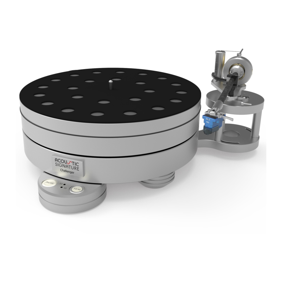
- Page 4 Packing Verpackung Parts Teile Challenger chassis Challenger Chassis Control unit Bedienteil Motor unit Motordose Tool set Toolset Power cord Netzanschlusskabel Patch cable RJ45 Patchkabel RJ45 Platter Plattenteller Digital Motor Control DMC1 Digitale Motorsteuerung DMC1 Drive belt (not shown) Antriebsriemen (nicht dargestellt) Leather mat (not shown) Ledermatte (nicht dargestellt) Manual (not shown)
- Page 5 Setup Aufbau Preparation Vorbereitung To avoid transport damages the Challenger Um Transportschäden zu vermeiden wird der comes in a carefully designed packing and is Plattenspieler sorgfältig verpackt und teilweise partially preassembled. zerlegt geliefert. We recommend to have a plane area of about Für den Aufbau benötigen Sie eine ebene Fläche 400x600mm / 16x24 square inch for setup.
- Page 6 Mounting the platter Teller montieren Take away the cover strip over the bearing hole. Entfernen Sie den Schutzaufkleber über der La- gerbohrung. Insert the platter carefully into the bearing. Take care that it slides in slowly and easily. Setzen Sie nun den Plattenteller vorsichtig in die Lagerbohrung ein und senken ihn ab.
- Page 7 Place the motor unit Motordose positionieren Place the motor unit at an optional position Die Motordose kann an jeder beliebigen freien around the platter. Normally the motor unit is Stelle um den Teller herum aufgestellt werden. placed on the opposite side of the tonearm. Normalerweise befindet sie sich gegenüber dem The distance of the motor unit (its axis) to the Tonarmausleger.
- Page 8 Connecting the Challenger Anschlüsse am Challenger Connect the Challenger in 3 steps: Schliessen Sie den Challenger in 3 Schritten an: - Patch cable RJ45 - Patchkabel RJ45 - Motor cable - Motorkabel - Power cord - Netzkabel See picture below for correct positions of connec- Beachten Sie das unten stehende Bild für die La- tions.
- Page 9 Operating the Challenger Bedienung des Challenger Position the Control unit centrically between the Positionieren Sie das Bedienfeld nach dem An- front feet, so that both buttons are easily acces- schliessen zentrisch zwischen die vorderen Füsse, sible. so dass beide Tasten gut erreichbar sind. On the left top side of the Control unit are 2 push Vorne links auf der Oberseite des Bedienfeldes buttons marked with ON/OFF and 33/45.
- Page 10 3 height adjustable feet 3 höhenverstellbare Füsse Platter: Teller: Aluminum platter Ø299mm x 50mm, weight: 9kg Aluminium-Teller Ø299mm x 50mm, Gewicht: 9kg Acoustic Signature Made by AS-Distribution GmbH Hillenbrandstrasse 10 D-73079 Süssen / Germany Tel: +49 7162 9474450 www.acoustic-signature.com E-Mail: info@as-distribution.de...
- Page 11 For your notes Für Ihre Notizen...
Need help?
Do you have a question about the CHALLENGER 2018 and is the answer not in the manual?
Questions and answers