HySecurity StrongArm M30 Programming & Operation Manual
Smart touch controller
Hide thumbs
Also See for StrongArm M30:
- Manual (106 pages) ,
- Programming and operations manual (106 pages)
Table of Contents
Advertisement
Quick Links
CRASH
StrongArm M30 and StrongArm M50
Programming & Operations Manual with Hy-
Security Smart Touch Controller
This document provides Important Safety Information, specifications, and references along with an
overview of programming user and installer menu options, designing vehicle loop layouts, trouble-
shooting, and maintaining the gate operator.
Advertisement
Table of Contents
Troubleshooting

Subscribe to Our Youtube Channel
Related Manuals for HySecurity StrongArm M30


Summary of Contents for HySecurity StrongArm M30
- Page 1 CRASH StrongArm M30 and StrongArm M50 Programming & Operations Manual with Hy- Security Smart Touch Controller This document provides Important Safety Information, specifications, and references along with an overview of programming user and installer menu options, designing vehicle loop layouts, trouble-...
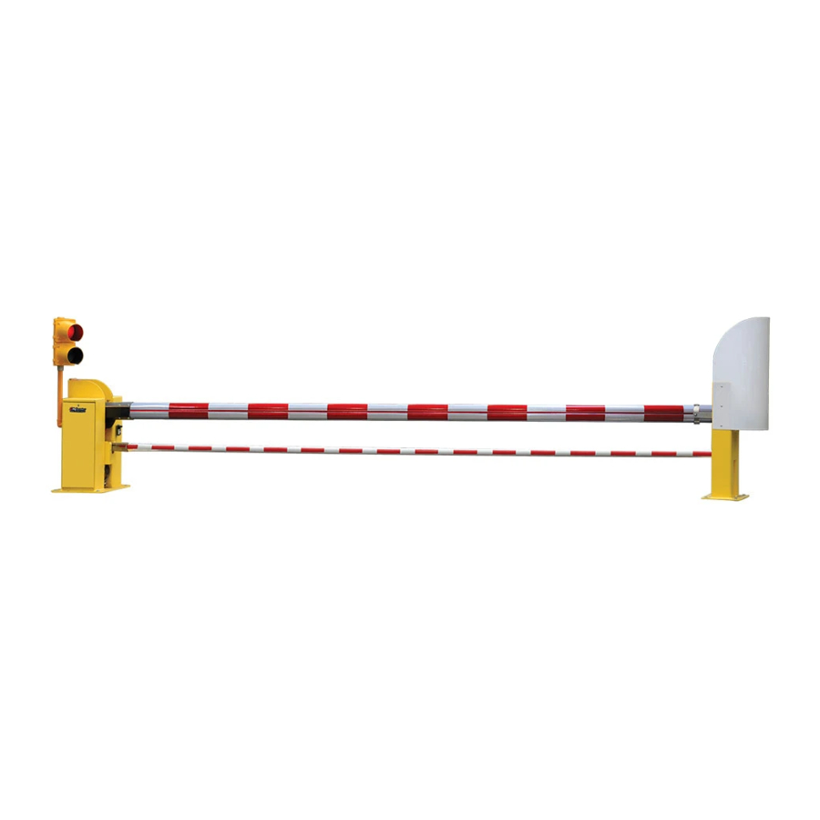
- Page 3 StrongArm M30 Components ® Security Smart Touch Controller Photo eye Display Open Reset Previous Board & Close Next Green = Operate Keypad Yellow = Program = Fault Stop Program Select Power Module Smart Touch Controller Electronics inside Pivot Post (wire connections not shown)
- Page 4 StrongArm M50 Components The same call outs used on the StrongArm M30 match the StrongArm M50 components. To review the exploded parts and terminology, refer to the previous page. The StrongArm M50 differs in the size and strength of its components.
-
Page 5: Table Of Contents
Notices and Bulletins ............................Safety-2 Supplemental Documents ............................ Safety-2 IMPORTANT SAFETY INFORMATION .......................Safety-2 StrongArm M30/M50 Fortified Crash Barrier Arms ..................Safety-3 Risk Assessment and Site Preparation ......................Safety-3 Safety - Installer’s Responsibility ........................Safety-3 Safety - Installer’s Responsibility, continued ...................... Safety-4 Safety - Owner/User Responsibility ........................ - Page 6 M30/M50 Hydraulic Cylinder Maintenance ......................... 8-4 M30/M50 Bearing Maintenance & Lubrication ......................8-5 Clock Battery Replacement ............................8-5 ....................a1 eference ection M30/M50 WiringDiagram ............................A2 b ......................b1 PPenDix Wire Sizing and Runs ..............................B1 StrongArm M30/M50 Wiring Chart (Incoming Power) ....................B2...
- Page 7 Vehicle Detector Loop Configurations ........................C2 StrongArm M30/M50 Vehicle Loop Requirements ....................C2 StrongArm M30/M50: Sequenced Gates #1 - Slide Gate Loop Layout ..............C4 StrongArm M30/M50: Sequenced Gates #2- Slide Gate Loop Layout ..............C5 StrongArm M30/M50: Sequenced Gates #1 - Swing Gate Loop Layout ..............C6 StrongArm M30/M50: Sequenced Gates #2 - Swing Gate Loop Layout ..............
- Page 9 Qualified HySecurity distributors are experienced and trained to assist in resolving any problems. For the name of a qualified distributor near you, call HySecurity at 800-321-9947. Before contacting your distributor or HySecurity Technical Support, obtain the serial number of your operator.
-
Page 10: Notices And Bulletins
Start the operator only when the travel path of the M30/M50 Arm is clear. Make sure the automatic StrongArm M30/M50 system is installed to reduce the risks of entrapment. Verify the StrongArm M30/M50 is installed to comply with all safety standards and local and federal regulations. -
Page 11: Strongarm M30/M50 Fortified Crash Barrier Arms
• The StrongArm M30 is certified crash tested per ASTM F2656-07 to a M30-P1 rating which means it has the capabil- ity to stop a 15,000 lbs (6.8 metric tons) medium-duty truck traveling at 30 mph (48.3 km/h) and arrest the vehicle within 3.3 feet (1 meter) of penetrating the barrier arm. - Page 12 • Vehicle detector loop size and placement are critical to ensure the proper and safe function of the StrongArm M30/ M50. Review and follow the loop plan drawings in this manual. Refer to “Loop Design” on page 1.
-
Page 13: Hand Pump Operation
Do not remove lighting, traffic signal wiring, bumpers or any other safety features. • Test the barrier arm monthly. Specifically, test the photo eye function. The StrongArm M30/M50 must stop or reverse when an object blocks the photo eye beam. - Page 14 3. The barrier arm will maintain its position whenever you stop pump- Hydraulics Cover Panel ing. Knurled knob Figure S-1 4. Continue pumping until the arm reaches full closed (horizontal) position. Hand pump Figure S-2 Safety-6 D0433 Rev. C StrongArm M30/M50: Programming & Operations Manual www.hysecurity.com...
-
Page 15: Safety Notices
The gear oil and pump pack fluid found in HySecurity crash barriers can be recycled. If the fluids are mixed or contaminated with any solvents or other chemicals, they become hazardous waste. Hazardous waste requirements for storage and disposal must be followed. -
Page 16: Ac Power Connection
The StrongArm M30 and StrongArmM50 have separate Installation Instructions that explain how to connect to AC power. For reference purposes, the same information is provided below. DANGER Turn OFF AC power at the source (circuit breaker panel) before accessing the wires in the StrongArm M30 or StrongArm M50. -
Page 17: Arm Position Sensor
An innovative approach to sensing the position of the barrier arm is standard for all StrongArm Fortified Crash Barrier Arms. No physical limit switches exist. The StrongArm M30/M50 is programmed to recognize the barrier arm open and close limits based on certain criteria and sets them accordingly. The Learn Close Limit display appears the first time power is supplied to the operator. -
Page 18: Adjusting The Close Limit - User Menu
2. If further adjustment is needed, take steps 1 through 4 until the close limit is set at the desired location. If a larger adjustment is required, consider using LL (Learn Limits) in the “Installer Menu: Table 2.” D0433 Rev. C StrongArm M30/M50: Programming & Operations Manual www.hysecurity.com... -
Page 19: Display & Menu Options
NOTE: Use a laptop computer at your place of business to conveniently download the free START software and most current software version from www.hysecurity.com before heading out into the field. This makes it easy to adjust settings using a laptop. - Page 20 Navigating within the program menus is easy once you learn how the keypad buttons function. Refer to the following chart. StrongArm M30/M50: Program Mode Navigation Buttons To change that data To navigate through the To choose what appears...
- Page 21 The type of information that may scroll across the display includes: interlocked or sequenced gate (if applicable), operator type (OT), gate handing (RH or LH), clear opening (CO), Usage Class (UC), buss voltage, and life cycle counter. ot 8 Co 22 Example of Operator Status Displays www.hysecurity.com Program & Run Modes D0433 Rev C .
-
Page 22: Program Mode Navigation
A setting of 1 also deactivates the automatic close timer and causes its menu to disappear. The Hold to Close replaces the Close Timer display as the User Menu entry display. D0433 Rev. C StrongArm M30/M50: Programming & Operations Manual www.hysecurity.com... - Page 23 0 setting. Adjusts the contrast of the display. Available settings LCD Contrast 0 through 9 from low contrast 0 to 9 high contrast, with a factory default setting of 5. www.hysecurity.com Program & Run Modes D0433 Rev C .
-
Page 24: Installer Menu
Ct 0 The Installer Menu options provide more advanced configurations for the StrongArm M30/M50 operators. Access to the Installer Menu is through the User Menu. The navigational buttons are the same in both menu modes. Refer to “Program Mode Navigation” on page 4-2. -
Page 25: Installer Menu: Table 2
CAUTION: If factory defaults are restored, any customized menu settings will need to be repro- grammed. You can save your customized menu setting using a PC laptop & S.T.A.R.T. www.hysecurity.com Program & Run Modes D0433 Rev C . - Page 26 FAL 2 alert which requires a Stop or Reset button COM/ PHOTO EYE press to re-enable any function that has been CLOSE (#19) triggered. All other HySecurity operators are fac- tory set for normal open (a setting of zero). 0 = Normally Open Edge...
- Page 27 Free Exit detector. The optional setting of (#8) Free Exit Loop Detector 1, creates an automatic close function if a vehicle COM or connection triggers and then backs off the Free Exit Loop to HY-5A detector detector. www.hysecurity.com Program & Run Modes D0433 Rev C .
- Page 28 0 = Run mode Controls the HY-5A Outside Obstruction Loop HY-5A 1 = Show frequency detector. Out Obs Set Loop 2 = Show call level 0-7 3 = Set Frequency 4-10 D0433 Rev. C StrongArm M30/M50: Programming & Operations Manual www.hysecurity.com...
- Page 29 0 = Run mode Controls the HY-5A Reset Loop detector. HY-5A 1 = Show frequency Reset Loop Set 2 = Show call level 0-7 3 = Set Frequency 4-11 www.hysecurity.com Program & Run Modes D0433 Rev C .
-
Page 30: Resetting Open And Close Limits
3. Press Stop twice to preserve the open stop location. The buzzer chirps twice and the full open stop is retained in memory. NOTE: If you need to fine-tune the barrier arm’s position, review the steps found in “Adjusting the Close Limit – USER Menu” on page 3-2. 4-12 D0433 Rev. C StrongArm M30/M50: Programming & Operations Manual www.hysecurity.com... -
Page 31: Setting The Close Timer
Close. It will close a second or two faster than normal operation and ignore any photo eye, vehicle loop, or other safety device inputs. NOTE: If additional accessories are to be added, read about STC Inputs on page 4-19. 4-13 www.hysecurity.com Program & Run Modes D0433 Rev C . - Page 32 4-14 D0433 Rev. C StrongArm M30/M50: Programming & Operations Manual www.hysecurity.com...
- Page 33 CLOSE DIRECTION Red = alert, fault, or error DO NOT USE - 20 DO NOT USE CHARGER Charger AC Loss - 21 AC LOSS HySecurity HY-5A Shadow / 24V DC Gate Lock Interlock - 22 SPARE INPUT MX000585 Reset* Socket...
- Page 34 7 available terminals can be LIMIT DUAL GATE RADIO OPTIONS used to draw the 3A maximum. OPEN +24V +24V EDGE Smart Touch Controller LOOP Not to Scale D0433 Rev. C StrongArm M30/M50: Programming & Operations Manual www.hysecurity.com...
- Page 35 Ystems The StrongArm M30/M50 provides a 2-wire, serial interface (RS-485 connection) which allows remote access to one or more operators. With software protocols provided by HySecurity, bi-directional status updates and control commands are easily integrated with a central controller (computer or server) which becomes the master to the connected operators. Up to 31 physical operators can be polled from the central master command station.
-
Page 36: Mart Ouch Ontroller
Time Clock Open active via an interlocked pair can be configured as the Time Clock contact or time clock command. Open (TC 0) input. Refer to the “Install- er Menu: Table 2.” D0433 Rev. C StrongArm M30/M50: Programming & Operations Manual www.hysecurity.com... -
Page 37: Vehicle Detector Logic
Jumper to +24 COM. See CO setting in “Installer Menu: Table 2.” Fire Dept Open Emergency override opens gate. Jumper to +24 COM. See “Installer Tact Button Menu: Table 2.” FO STC Inputs www.hysecurity.com Smart Touch Controller D0433 Rev C . - Page 38 6 to 8 seconds 5 to 7 seconds SlideDrvier 50VF2 2.2 fps (26 in per sec) 3 fps (91 cm/s) SlideDriver 50VF3 3 fps (91 cm/s) 3 fps (91 cm/s) Variable Speed Drive D0433 Rev. C StrongArm M30/M50: Programming & Operations Manual www.hysecurity.com...
- Page 39 PHOTO EYE OUTSIDE LOOP OPEN DIRECTION DO NOT USE STATUS PHOTO EYE CLOSE DIRECTION DO NOT USE CHARGER AC LOSS HySecurity HY-5A SPARE INPUT MX000585 CENTER LOOP VERSION Photo eye EMERG CLOSE FIRE DEPT OPEN 4-wire connection: Smart Touch Controller...
- Page 40 Activated if the Arm is forced off the closed limit Relay 1 or 2 switch and the operator is not able to restore the Arm to full closed position within four seconds. This alarm resets itself in 30 seconds. D0433 Rev. C StrongArm M30/M50: Programming & Operations Manual www.hysecurity.com...
- Page 41 Inside Obstruction Vehicle Detector Active when the Inside Obstruction loops is tripped. Relay 1 or 2 output Reset Loop Detector output Activated when the Reset loop detector is tripped. Relay 1 or 2 www.hysecurity.com Smart Touch Controller D0433 Rev C .
- Page 42 HySecurity recommends that vehicle detectors be used for free open and obstruction sensing logic only. The exception is in parking or barrier arm applications where detectors may also be used to close the gate. In applications employing our swing, vertical lift, or sliding gate operators, closing logic cannot be used except when the anti-tailgate logic is employed.
- Page 43 The OOLD & IOLD can be individually set so that, if tripped while closing, the gate may pause only or reverse to reopen. The free exit detector input is blocked while the gate is closing. 5-11 www.hysecurity.com Smart Touch Controller D0433 Rev C .
- Page 44 Screw terminals for loop wire HY-5A Vehicle loop sensitivity levels explained on the front label. Metal pins fit into a socket on the Smart Touch Controller. HY-5A Vehicle Detector Module 5-12 D0433 Rev. C StrongArm M30/M50: Programming & Operations Manual www.hysecurity.com...
-
Page 45: Connecting Hy-5A Vehicle Detectors
NOTE: If there is any detector fault, the gate operator functions as if the detector is triggered. Pressing the RESET button: Š Clears any errors Š Tunes the detectors on connected loops Š Un-installs any detectors that have been removed 5-13 www.hysecurity.com Smart Touch Controller D0433 Rev C . - Page 46 (such as with tractor-trailer trucks). Sensitivity settings 4 through 7 are the same as 0 through 3, but without the boost feature. 5-14 D0433 Rev. C StrongArm M30/M50: Programming & Operations Manual www.hysecurity.com...
-
Page 47: Dual Gate Systems
NOTE: The operators do not have to be of the same type, but both need to have the most current and up-to- date software version installed on the Smart Touch Controller. A StrongArm M30/M50 can be interlocked with a SlideDriver™ to provide both crash and personnel security. The STC software integrates seamlessly between operators. - Page 48 Smart Touch Controller LIMIT DUAL GATE RADIO OPTIONS LIMIT DUAL GATE RADIO OPTIONS OPEN +24V +24V EDGE OPEN +24V +24V EDGE Wire Diagram: Interlocked Pair of Operators using DUAL GATE Wiring D0433 Rev. C StrongArm M30/M50: Programming & Operations Manual www.hysecurity.com...
-
Page 49: Dual Or Sequenced Gates: Power, Software & Accessory Requirements
RESET button. For example: h 4.3 (“h” = Hysecurity, “4.31” = software version). • Keep the most current software loaded. It is available at http://www.hysecurity.com. Make it part of your mainte- nance routine to check for and install software updates on a regular basis. -
Page 50: Connecting Sequenced Gates
The operators do not have to be of the same type, but both need to have the most current and up-to-date software version installed on the Smart Touch Controller. A StrongArm M30/M50 can be sequenced with a SlideDriver to provide both crash and personnel security. The inherent STC software integrates seamlessly between operators and software protocols and allows RS-485 communication for networked security sys- tems. - Page 51 SG 1 = Sequential Gate #1 configuration SG 2 = Sequential Gate #2 configuration NOTE: Set both operators on the site to the same number. See the site designs on the following pages. www.hysecurity.com Program & Run Modes D0433 Rev C .
- Page 52 The Traffic Control Gate maintains functionality while the Security Gate defaults to open until communication is restored (or the Security Gate is manually closed). Drawings are not to scale. © 2012 D0433 Rev. C StrongArm M30/M50: Programming & Operations Manual www.hysecurity.com...
- Page 53 Sequential Gate #2 StrongArm M30/M50 with Slide Gate Site Diagram Optional access control devices (card reader, etc.) Configuration steps: 1. Set both gate operator’s Installer Menu item to SG 2.** 2. Configure the Close Timer (CT). SECURITY SLIDE GATE Operator Positioning Dimension “A”...
- Page 54 D0433 Rev. C StrongArm M30/M50: Programming & Operations Manual www.hysecurity.com...
-
Page 55: Troubleshooting
These diagnostic messages can be retrieved for analysis purposes via optional S.T.A.R.T. software. NOTE: S.T.A.R.T. Configuration and Diagnostic software is available at no charge from www.hysecurity.com. Identification and a description of the error, alert, and fault messages that appear on the Smart Touch Controller display is provided on the following pages. - Page 56 4s, an alert will be sound- ed. Check for cylinder leakage, misadjusted/failed open limit, outside pressure (wind, fallen trees) trying to force the M30/M50 Arm closed. D0433 Rev. C StrongArm M30/M50: Programming & Operations Manual www.hysecurity.com...
- Page 57 2 chirps per second Replace the 3V disc battery that controls the internal clock, with Bad 3V ‘coin’ battery every 15 seconds the AC power turned off. Use a CR2032 battery. www.hysecurity.com Program & Run Modes D0433 Rev C .
- Page 58 Internal error between the STC board and the VFD. Check STC – VFD Communication once per minute cable connections and wiring. Make sure both units are working Error properly. D0433 Rev. C StrongArm M30/M50: Programming & Operations Manual www.hysecurity.com...
- Page 59 3 chirps per second Not applicable Slowdown Switch Failure once per minute 1 chirp once every Not applicable to StrongArm M30/M50. Maximum Run Fault 15 seconds 2 chirps per second “Supervised” means the STC must see the photo-eye NC con-...
-
Page 60: Electrical Issues
Arm open and close. General maintenance recommends scheduled inspection of all fasteners to make sure they are tightened securely and torqued to proper specifications. For torque specs, refer to General Maintenance. D0433 Rev. C StrongArm M30/M50: Programming & Operations Manual www.hysecurity.com... -
Page 61: Hydraulic Issues
NOTE: If the gate speed must be changed, contact your HySecurity distributor. Extremely cold weather is unlikely to seriously affect the Arm speed because HySecurity employs a special grade of hydraulic fluid (Uniflow), which maintains a linear viscosity over a broad temperature range. This high quality fluid combined with other design considerations allow HySecurity to rate its operators for service in ambient temperatures of -40°F to 158°F (-40°C to... - Page 62 If the gate only opens, the Directional Valve is probably stuck and needs to be replaced. If the gate only closes, the Directional Valve Coil is not being energized or is defective. D0433 Rev. C StrongArm M30/M50: Programming & Operations Manual www.hysecurity.com...
-
Page 63: General Maintenance
S.T.A.R.T. software. The free S.T.A.R.T. software is conveniently located at www.hysecurity.com. Instructions for downloading S.T.A.R.T. are on the website, as well. HySecurity Serial RS-232 communication cable. Be sure to install the USB driver in your laptop, if you are using the HySecu- rity RS-232 to USB adapter. -
Page 64: Installing S.t.a.r.t. Software, Continued
ContInued 8. When the download is complete, log out of the HySecurity website. Shortcuts for the S.T.A.R.T. and STC History Logs appear on your laptop’s desktop. *NOTE: If the operating system on your laptop is VISTA or Windows 7, you must first disable the “User Account Control Settings”... -
Page 65: Mechanical Maintenance
NOTICE: Before checking the internal mechanisms of the operator, turn off all power switches. The mechanical maintenance for the StrongArm M30/M50 is not in depth or difficult, but should be performed on a routine basis. The operator chassis is zinc plated, but some environments may speed corrosion of this plating. -
Page 66: M30/M50 Hydraulic Cylinder Maintenance
The contents of the hydraulic cylinder are under pressure. Close the Arm prior to making any brake adjustments or disassembly to the manifold at the base of the hydraulic cylinder. Failure to close the arm may result in personal injury. Bottom Pin D0433 Rev. C StrongArm M30/M50: Programming & Operations Manual www.hysecurity.com... - Page 67 Replace the battery about every five years (or as needed) with a DL 2025, DL 2032, or CR 2025, or CR 2032 battery. www.hysecurity.com Program & Run Modes D0433 Rev C .
- Page 68 D0433 Rev. C StrongArm M30/M50: Programming & Operations Manual www.hysecurity.com...
-
Page 69: Reference Section
This section provides illustrations that are useful to refer to during the prep and install phases. The last page presents an installer’s checklist: an overview of the steps required to successfully complete the installation of the StrongArm M30/M50 Fortified crash barrier arm operator. - Page 70 IrIng Iagram VEHICLE DETECTOR VEHICLE DETECTOR VEHICLE DETECTOR VEHICLE DETECTOR STOP/BUZZER WIEGAND FREE INSIDE OUTSIDE SHADOW EXIT OBSTR OBSTR RESET MOTOR USER 1 USER 2 RS232 DISPLAY USER 3 D0433 Rev. C StrongArm M30/M50: Programming & Operations Manual www.hysecurity.com...
- Page 71 For ½ hp through 5 hp motors Supplying a StrongArm M30/M50 operator with the right electrical service is crucial to the performance of the operator and the life of its electrical components. If the wire size used is too small, the voltage loss, especially during motor startup, will prevent the motor from attaining its rated horsepower.
- Page 72 1580 (482m) 4380 (1335m) 5300 (1615m) 990 (302m) 1090 (332m) 2280 (695m) 2530 (771m) 6990 (2130m) 8470 (2582m) 1560 (475m) 1730 (527m) 3620 (1103m) 4000 (1219m) 11,070 (3374m) 13,400 (4084m) D0433 Rev. C StrongArm M30/M50: Programming & Operations Manual www.hysecurity.com...
- Page 73 “all clear” signal to close the gate which could cause damage to vehicles or injury to personnel. Loop dimension too small to detect high bed vehicle Properly size loops for the type of vehicles using your site www.hysecurity.com Loop Installation, Detection, & Layout D0433 Rev C .
- Page 74 HySecurity automatic gate operators can be triggered to open or close through a variety of devices: integrated pushbutton control, remote access control, or a vehicle detection loop. An individual can affect normal open and close functions by: •...
- Page 75 The Smart Touch Controller has three available settings when an Obstruction Loop is tripped dur- ing closure: Reverse open, pause only, continue closing. To adjust the setting. read Section 4: Program Mode. StrongArm M30/M50 Fortified Crash Barrier Arm Vehicle Loop Layout : Single or Bi-directional Traffic...
- Page 76 (or the Security Gate is manually closed). Dimension “E” = 10 to 12 feet (305 cm to 366 cm) if an access control device is employed. Drawings are not to scale. D0433 Rev. C StrongArm M30/M50: Programming & Operations Manual www.hysecurity.com...
- Page 77 #2- s trong equenCed ates lIde aYout Sequential Gate #2 StrongArm M30/M50 with Slide Gate Vehicle Loop Layout Optional access control ntro ntro OUTSIDE devices (card reader, etc.) er, e r, e OBSTRUCTION Configuration steps: LOOP 1. Set both gate operator’s (OOLD for both Installer Menu item to SG 2.**...
- Page 78 Dimension “E” = 10 to 12 feet (305 cm to 366 cm) if an access control device is employed. © 2012 Drawings are not to scale. D0433 Rev. C StrongArm M30/M50: Programming & Operations Manual www.hysecurity.com...
- Page 79 #2 - s trong equenCed ates wIng aYout Sequential Gate #2 StrongArm M30/M50 with Swing Gate Vehicle Loop Layout Optional access control ntro ntro devices (card reader, etc.) er, e r, e OUTSIDE OBSTRUCTION Configuration steps: LOOP 1. Set both gate operator’s (SLD: Shadow Loop Installer Menu item to SG 2.**...
- Page 80 Dimension “E” = 10 to 12 feet (305 cm is restored (or the Security to 366 cm) if an access control device is employed. Gate is manually closed). © 2012 Drawings are not to scale. D0433 Rev. C StrongArm M30/M50: Programming & Operations Manual www.hysecurity.com...
- Page 81 #2 - B trong equenCed ates arrIer aYout Sequential Gate #2 StrongArm M30/M50 with Barrier Arm rm M30/M50 with Ba Vehicle Loop Layout Optional access control ntro ntro devices (card reader, etc.) er, e r, e (OOLD for Security Gate) Configuration steps: 1.
-
Page 82: Strongarm M30/M50 Wiring Chart (Incoming Power)
HySecurity Gate, Inc. Federal copyright law prohibits the reproduction, distribution, or public display of copyrighted materials without the express written permission of the copyright owner, unless fair use or other exemption under copyright law applies. Additionally, HySecurity Gate, Inc.
Need help?
Do you have a question about the StrongArm M30 and is the answer not in the manual?
Questions and answers