Table of Contents
Advertisement
The following instructions are intended to assist the user in replacing the Smart DC Controller (SDC) in HySecurity
electromechanical gate operators. Please read all assembly instructions before installing the kit.
REQUIRED TOOLS
„ Phillips head screwdriver
„ Needle nose pliers
Always ensure operator firmware is updated to
latest available version. The latest available version
is at
www.hysecurity.com/contact-us/technical-
support/operator-software/
HySecurity website by clicking:
TechSupport Resources Operator Software
Current Operator Software Versions
UL 325 - 2018 requires that gate operators monitor
external entrapment protection sensors. Affects
all HySecurity gate operators manufactured
beginning in 2016.
CAUTION
Remember the operator may have unique user
& installer menu settings on the existing board.
Prior to replacing the SDC board, compare
the programmed settings that appear in the
existing board's display to the default settings
shown in the "Smart DC Controller Worksheet"
on page 2 and note any changes. If you have
a bi-parting gate system, be sure the software
version in both operators is identical.
TECHNICAL SUPPORT
For technical support, call your installer or
authorized HySecurity distributor. Obtain the serial
number of your operator before calling. For the
name of a distributor near you, contact HySecurity
at 800-321-9947.
For more information regarding how HySecurity
is handling monitoring of external entrapment
protection sensors, go online to:
www.hysecurity.com/gatesafety
D0360 REV. I ©2018
or by naviagting the
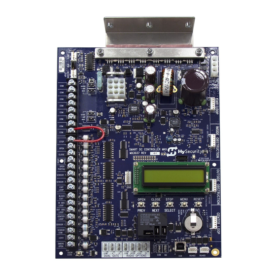
SMART DC INSTALLATION INSTRUCTIONS
MX3037, MX3037R, MX001457
Smart DC Controller Installation Instructions
COPY USER & INSTALLER MENU SETTINGS
Examples of the settings that need to be
reprogrammed when you replace an SDC board
include: Build Year, Operator Type, Usage Class,
Gate Handing and Learn Limits. Other settings
may include Gate Weight, Close Timer, and
accessory configurations. The operator can be
reprogrammed on site by entering the User or
Installer Menu via the Menu buttons or using
S.T.A.R.T. software and a laptop PC to save/load
existing settings. If you need more information,
see "Technical Support" on page 1.
Create a backup copy of the gate operator
configurations, using one of two methods:
z Use a PC laptop and S.T.A.R.T. with a USB cable
(Type A to Type B).
z Use the "Smart DC Controller Worksheet" on
page 2. Go through each menu item and
write the number that appears in the display
into the chart's column titled, "Display Setting."
TWO METHODS TO RECORD USER &
INSTALLER MENU SETTINGS
Figure 1. S.T.A.R.T. Display
User Menu Item*
CT _ Close Timer
HC _ Hold to Close
HO _ Hold to Open
AP _ AC Loss function
RO_ Radio Open/Close
BF _ Warn Before Operate
FA _ Forced Open Alert
DA _ Drift Close Alert
PE _ Photo Eye Alignment
CL_ Set Clock (24 hour)
LD_ LCD Contrast setting
CA_ Close Limit Adjustment
AL_ Flash on Close Limit
DS_ Diagnostic Log
*NOTE: The items shown in the user & installer menu charts may or may not appear on
your operator's display. The menu items that appear are dependent on the operator type
Installer Menu Item*
OT _ Select Operator Type
MN _ Model Number
LL _ Learn Limits
UC _ Usage Class
SH _ Gate Handing
WT _ Gate Weight (lbs)
LN _ Gate Length (Feet)
OS _ Open Speed
CS _ Close Speed
FD _ Load Factory Defaults
DG _ Dual Gate
SG _ Sequenced Gate
CH _ Charger Type
FO _ Fire Dept. Open
Figure 2. SDC Programmable Menu Items Settings
Default Setting
Display Setting
(write it down here)
0
Installer Menu Item*
Default Setting
Display Setting
Notes:
0
(write it down here)
0
SE _ IES Sensitivity
2
0
SS _ Inherent sensor Stop
0
0
LC _ Leaf Delay Close
0.0 Secs
2
LO_ Leaf Delay Open
0.0 Secs
0
RT _ Maximum Run Timer
30 Secs
0
PO _ Partial Open distance
0
0
EC _ Eye Close Logic
0
0
EO _ Eye Open Logic
0
5
GR _ Gate Edge Logic
0
0
SR _ IES Sensor Logic
1
1
PC _ Photo Eye Contact NC
0
0
GC _ Gate Edge Output NC
0
DT _ Disable Free Exit
0
OR _ Outside Obstr Loop
1
Default Setting
Display Setting
Notes:
IR _ Inside Obstr Loop
1
(write it down here)
HD _ Center Loop Hold
1
0
DL _ Detector Logic
1
0
CR _ RLD Reverse Open
0
0
CB _ RLD Disables ELD
0
0
CP _ Counts PBO
0
EB _ ELD Back off - Detector
0
0
0
R1 _ Relay 1 Logic - disabled
0
0
R2 _ Relay 2 Logic - Close Limit
1
5
TL _ Gate Open alert
2
5
LT _ Loitering alert
3
SA _ STC Address
0
0
0
ELD _ Exit Loop Set
0
0
ILD _ Inside Obstr. Loop Set
0
0
OLD _ Outside Obstr. Loop Set
0
0
CLD _ Center Loop Set
0
www.hysecurity.com |
1
Advertisement
Table of Contents

Subscribe to Our Youtube Channel
Related Manuals for HySecurity MX3037R


Summary of Contents for HySecurity MX3037R
- Page 1 MX3037, MX3037R, MX001457 Smart DC Controller Installation Instructions The following instructions are intended to assist the user in replacing the Smart DC Controller (SDC) in HySecurity electromechanical gate operators. Please read all assembly instructions before installing the kit. REQUIRED TOOLS COPY USER &...
- Page 2 NOTE: Available menu items are dependent on operator type NOTE: Available menu items are dependent on operator type and programming configurations or options. and programming configurations or options. | www.hysecurity.com SMART DC BOARD INSTALLATION INSTRUCTIONS D0360 REV. I ©2018...
- Page 3 REPLACING THE SMART DC CONTROLLER To replace a SDC board, take the following steps: Back up (make a copy) of the existing board’s menu settings. See "www.hysecurity.com/gatesafety" on DC POWER page 1 and "Smart DC Controller Worksheet" on page 2.
- Page 4 PC and S.T.A.R.T. software NOTICE version 3.00 or higher to reset the operator Make sure you designate the correct operator type. If necessary, contact HySecurity Technical type! Refer to Table 3. Support at 800-321-9947. Load operator’s custom settings that you saved in the S.T.A.R.T.
- Page 5 (edge sensors and photo eyes) Pre-2016 Post 2016 Label Build Year (BY 1) Build Year (BY 2) for all entrapment zones. HySecurity gates monitor MX3978-02 MX3978-01 normally closed (NC) sensors. Wire your NC Figure 6. SDC Board BY-Lable Changes sensors to SENSOR input terminals (SENSOR 1, SENSOR 2, or SENSOR 3) on Smart DC Controllers.
- Page 6 SETTING THE BUILD YEAR Set the Build Year to 1 for HySecurity gate operator’s manufactured prior to 2016. Set the Build Year to 2 for gate operators manufacutured between 1/1/2016 and 7/31/2018. Set the Build Year to for gate operators manufactured after 7/31/2018.
- Page 7 HydraWedge SM50 2 or 3 NOTE: For more information, refer to the Quick Start Supplement describing changes to HySecurity software due to UL 325 - 2016 Standard of Safety updates. Review the information regarding monitoring of external entrapment protection sensors online at www.hysecurity.com/gatesafety D0360 REV.
- Page 8 Only appears when BY is set to 2 or higher. NOTE: Build Year is an Installer Menu item added in 2016 and defines HySecurity gate operators as having monitoring capabilities for external entrapment protection sensors per UL 325 Standard of Safety. See page 6 | www.hysecurity.com...
Need help?
Do you have a question about the MX3037R and is the answer not in the manual?
Questions and answers