Table of Contents
Advertisement
Advertisement
Table of Contents

Related Manuals for M5Stack M5STICKC PLUS


Summary of Contents for M5Stack M5STICKC PLUS
- Page 1 M5STICKC PLUS 2020 V0.01...
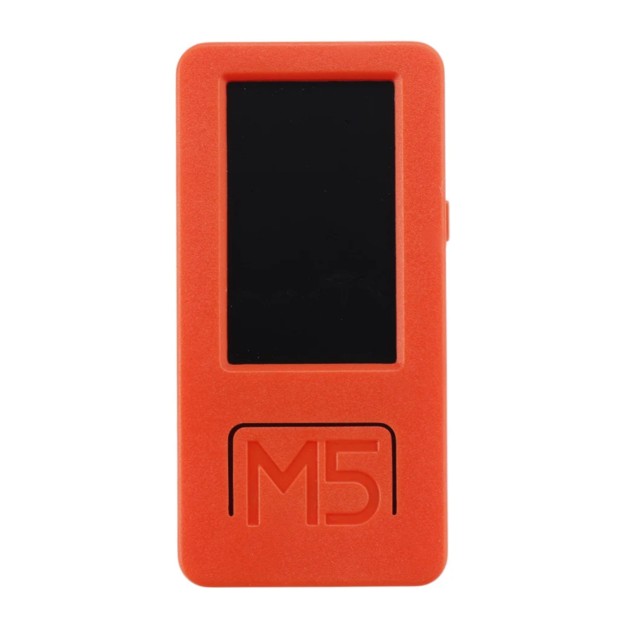
- Page 2 StickC PLUS is ESP32 board which based on ESP32-PICO-D4 module, with one LED and one button The board is made of PC+ABC. 1.1 Hardware Composition The hardware of M5StickC PLUS: ESP32-PICO-D4 module, TFT screen, IMU, IR transmitter, Red LED, Button, GROVE interface, TypeC-to-USB interface, Power Management chip and battery.
- Page 3 3-axis accelerometer in a small 3 mm x 3 mm x 0.75 mm 24-pin LGA package. Power Management chip is X-Powers's AXP192. The operating voltage range is 2.9V~6.3V and the charging current is 1.4A. M5StickC PLUS equips ESP32 with everything needed for programming, everything needed for operation and development...
- Page 4 2. PIN DESCRIPTION 2.1. USB INTERFACE M5CAMREA Configuration Type-C type USB interface, support USB2.0 standard communication protocol. 2.2. GROVE INTERFACE 4p disposed pitch of 2.0mm M5CAMREA GROVE interfaces, internal wiring and GND, 5V, GPIO32, GPIO33 connected.
- Page 5 3. FUNCTIONAL DESCRIPTION This chapter describes the ESP32-PICO-D4 various modules and functions. 3.1. CPU AND MEMORY ® ESP32-PICO-D4 contains two low-power Xtensa 32-bit LX6 MCU. On-chip memory comprising: 448-KB of ROM, and the program starts for the kernel function calls ⚫...
- Page 6 3.3. CRYSTAL • ESP32-PICO-D4 integrates a 40 MHz crystal oscillator. 3.4. RTC MANAGEMENT AND LOW POWER CONSUMPTION ESP32 uses advanced power management techniques may be switched between different power saving modes. (See Table 5). • Power saving mode - Active Mode: RF chip is operating. Chip may receive and transmit a sounding signal.
- Page 7 Functions in different power consumption modes: TABLE 5...
- Page 8 4. ELECTRICAL CHARACTERISTICS 4.1. LIMIT PARAMETERS Table 8: Limiting values 1. V IO to the power supply pad, Refer ESP32 Technical Specification Appendix IO_MUX, as SD_CLK of Power supply for VDD_SDIO.
- Page 9 UIFlow Quick Start This tutorial applies to M5StickC and M5StickC PLUS Burning tool Please click the button below to download the corresponding M5Burner firmware burning tool according to your operating system. Unzip and open the application. Windows10 MacOS Linux...
- Page 10 Firmware burning 1.Double-click to open the Burner burning tool, select the corresponding device type in the left menu, select the firmware version you need, and click the download button to download. 2.Then connect the M5 device to the computer through the Type-C cable, select the corresponding COM port, the baud rate can use the default configuration in M5Burner, in addition, you can also fill in the WIFI that the device will be connected to during the firmware burning stage information.
- Page 11 3.When the burning log prompts Burn Successfully , it means that the firmware has been burned. When first burning or the firmware program runs abnormally, you can click "Erase" to erase the flash memory. In the subsequent firmware update, there is no need to erase again, otherwise the saved Wi-Fi information will be deleted and the API Key will be refreshed.
- Page 12 AP hotspot configuration WiFi 1. Press and hold the power button on the left to turn on the machine. If WiFi is not configured, the system will automatically enter the network configuration mode when it is turned on for the first time. Suppose you want to re-enter the network configuration mode after running other programs, you can refer to the operation below.
- Page 13 A in the main menu interface to select the programming mode and wait till the right indicator of the network indicator to turn green in the programming mode page. Access UIFlow programming page by visiting flow.m5stack.com on a computer browser. API KEY Pairing API KEY is the communication credential for M5 devices when using UIFlow web programming.
- Page 14 up the LED indicator. (1. Drag the LED to light up the program block. 2. Splice to the Setup initialization program. 3 Click the Run button in the upper right corner) UIFlow Desktop IDE UIFlow Desktop IDE is an offline version of UIFlow programmer which does not require network connection, and can provide you with responsive program push experience.
- Page 15 After the app starts, it will automatically detect whether your computer has a USB driver (CP210X), click Install, and follow the prompts to finish installation. (M5StickC does not require a CP210X driver, so users can choose to install or skip) After the driver installation is complete, it will automatically enter the UIFlow Desktop IDE and automatically pop up the configuration box.
- Page 16 Click the power button on the left side of the device to restart, after entering the menu, quickly click the right button to select mode. Select the corresponding port, and the programming device, click OK to connect. BLE UART Function Description Establish Bluetooth connection and enable Bluetooth passthrough service.
- Page 17 Init ble uart name Initialize settings, configure Bluetooth device name. BLE UART Writre Send data using BLE UART. BLE UART remain cache Check the number of bytes of BLE UART data. BLE UART read all Read all data in BLE UART cache. BLE UART read characters Read n data in BLE UART cache.
- Page 18 FCC Statement Any Changes or modifications not expressly approved by the party responsible for compliance could void the user’s authority to operate the equipment. This device complies with part 15 of the FCC Rules. Operation is subject to the following two conditions: (1) This device may not cause harmful interference, and(2) This device must accept any interference received, including interference that may cause undesired operation.
Need help?
Do you have a question about the M5STICKC PLUS and is the answer not in the manual?
Questions and answers
Что делать если нрф24 не работает
If the NRF24 module is not detected when connected to the M5StickC Plus 2, check all the wiring to ensure proper connections.
This answer is automatically generated
Почему стик включается только когда стоит на зарядке