Advertisement
Quick Links
Advertisement

Related Manuals for Laguna Tools Smartshop CBX


Summary of Contents for Laguna Tools Smartshop CBX
-
Page 2: Table Of Contents
Table of Contents- Techncial Parameters: Page 3. Machine Briefing: Page 4. CBX Machine Footprint: Page 5. Machine Sight & Set-Up: Page 6-Page 10. Set-Up Ground Requirments for Installation: Page11-Page15. CBX Damage Notifications: Page 16. Installation Foundation Instructions: Page 17-Page 18. Cooling Water Requirements : Page 19-20. -
Page 3: Techncial Parameters
Technical Parameters-... -
Page 4: Machine Briefing
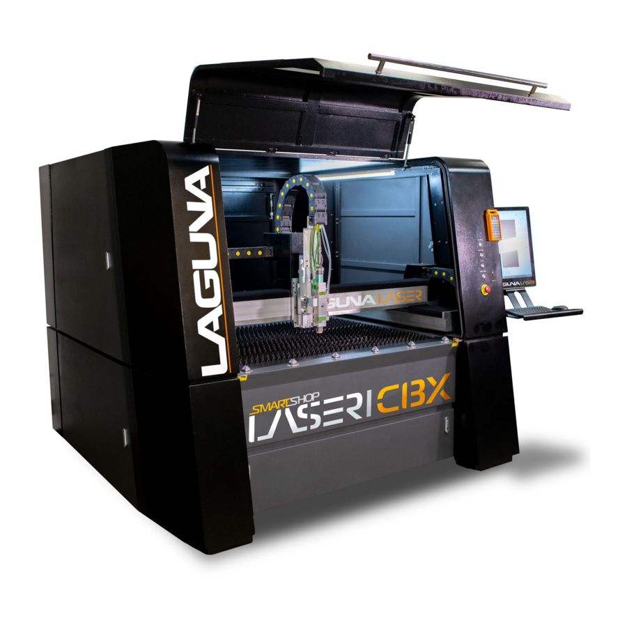
Machine Briefing- The Laguna Tools Smartshop® Laser/CBX is equipped with an enclosed working area preventing dust and eliminating light pollution. It also comes with a casting beam for increased rigidity and stability. For smooth operation, the CBX uses water/forced air cooling, a dust prevention system, and an automatic lubrication system to ensure longevity and consistency. - Page 5 CBW Fiber Laser Unit Footprint-...
-
Page 6: Machine Sight & Set-Up: Page
Machine Sight & Set Up-... - Page 7 Machine Sight & Set Up (Cont’d.)- 100.28 In 85.12 In...
- Page 8 Machine Sight & Set Up (Cont’d.)- 102.28 In. 74.02 In. 88.70 In. 83.66 In. The left and right sides, front and back sides of the machine, the Machine must be least 1.2 meters or 48 Inches from the workshop wall.
- Page 9 Machine Sight & Set Up (Cont’d.)- WALL 48.00 In. 48.00 In. WALL The left and right sides, front and back sides of the machine, the Machine must be least 1.2 meters or 48 Inches from the workshop wall.
- Page 10 Set-up Ground Requirements for Installation- Support Ground Requirements for Installation- The flatness of the ground is ± 10mm and it can withstand more than 6 tons of heavy objects. The foundation should be installed without large vibrations around it. Insert the steel plate in the ground according to the machine foot position drawing located under the Installation Foundation Instructions.
- Page 11 Ground Wire for Protection- The total number of ground pins is 3 or more. The material is pure copper or galvanized. The diameter of the ground pins is 15mm or .62 In. and the length is more than 1.5m or 5 Ft. Environmental Requirements- Requires a well-ventilated, dust-free, non-corrosive, and leak-free site environment.
- Page 12 4.) To Open Crate-Acquire some standard tools for taking apart the Crate. a.) Hammer. b.) Pry Bar. c.) Wire Cutters. d.) Cordless Drill.
- Page 13 5.) Cut all straps only on the Crate. 6.) Unscrew a series of Screws at the Base of Crate using a Cordless Drill.
- Page 14 7.) Unscrew and Remove Side Panels of Crate.
-
Page 15: Cbx Damage Notifications
CBX Damage Notification- 1.)The Machines are thoroughly tested before leaving any or our Laguna Tools Facilities, but that does not mean the Machines would not experience any damage in transit. 2.) Before one Signs the Bill of Lading (See Example Below) when the Trucking Company drops off... - Page 16 Installation Foundation Instructions- Steel Plate for Machine Foot Requirements-...
- Page 17 Installation Foundation Instructions- Installation Requirements- Installation Process- 1.) Making the Base Anchor, refer picture for size & specifications. 2.) Fix the Base Anchor to Cement Flooring with an Expansion Bolt, Type: M12*100, NO: 12 or a ½ Dia. X 4 1/2 In. Long Steel Expansion Bolt 3.) Placing the Machine on the Right Place of Base Anchor then Welding Area.
-
Page 18: Cooling Water Requirements
Cooling Water Requirements- Cooling circulating water requires Distilled or Deionized Water or Purified Water. Mineral Mater is prohibited. When the Ambient Temperature, (Ambient Temperature: The Air Temperature of any object or environment where equipment is stored.) is below 0 ° Celsius or 32 °... - Page 19 Note: It is recommended that all the above air switches have no leakage protection function. If it has a leakage protection function, the rated leakage protection current should not be less than 300mA, and it is recommended to be more than 500mA. If the rated leakage protection current is less than 300mA, it may cause the leakage protection to trip.
-
Page 20: Gas Standard Requirements
Gas Standard Requirements- Oxygen: With liquid oxygen, a vaporizer must be added to heat the liquid to a normal temperature gaseous state. The high-pressure liquid bottle withstands 4.5MPA, the vaporizer withstands 4.5MPA, flow rate: 1.0m3 / min, output pressure: 2.0MPA. Nitrogen: With liquid nitrogen, a vaporizer must be added to heat the liquid to a normal temperature gaseous state. - Page 21 Gas Standard Requirements (Cont’d.)- Schematic Diagram of Air System Note: The gas tank must be painted yellow and affixed with a safety warning sign. It must be used in strict accordance with the special gas operating regulations.
- Page 22 Installation & Operational Instructions/Steps- Step 1: Check the Machine is level. 1a.) Use the Leveling Instrument on the Y-Axis Rail Guide and a Beam Guide System to check if the machine is horizontal. Leveling Instrument Beam Guide System 1b.) If it is not horizontal, use a lifting jack to jack up the machine, then use a wrench to tighten the screw to adjust the height.
- Page 23 Installation & Operational Instructions/Steps- 1d.) Wipe the leveling instrument and guide rails with a clean cloth. 1e.) Put the leveling instrument on the Y-Axis rail guide and the Beam Guide to check if the machine is horizontal. If it is not horizontal, use a lifting jack to jack up the machine, then use a wrench to tighten the screw to adjust the height.
- Page 24 Installation & Operational Instructions/Steps- Step 2: Install Display Screen. 2a.) Install the display screen, first to install the display bracket, then screw the display screen to the bracket. Connect the VAG Signal Cable and the Screen Cable. 2b.) Install the display bracket 2c.) Screw the display screen to the bracket.
- Page 25 Installation & Operational Instructions/Steps- 2d.) Connect the VAG Signal Cable. 2e.) Connect the Power Cable and the Screen Cable.
- Page 26 Installation & Operational Instructions/Steps- Step 3: Water Chiller Installation 3a.) The water pipe of Water Chiller is connected the machine with the same label corresponding number. Connect both the “MAIN LOOP WATER INLET” and “MAIN LOOP WATER OUTLET” to the laser source, then connect both the “REFLECTOR PATH INLET”...
- Page 27 Installation & Operational Instructions/Steps- 3b.) Add or Fill 32L of requires of Distilled or Deionized Water or Purified Water to the water chiller tank until the water level gauge shows that the water chiller tank is full. Mineral Mater is prohibited.
- Page 28 Installation & Operational Instructions/Steps- Step 4: Install Nitrogen and Oxygen Tank- 4a.) The white tube is the trachea, the length can be cut according to their own needs, can be under pressure 2.8MPA. The oxygen and nitrogen interface sign are on the back of the machine. Connect the oxygen and nitrogen interface to corresponding gas cylinder.
- Page 29 Installation & Operational Instructions/Steps- Step 5: After installing the oxygen meter- Open the cylinder and fully open to ensure the air flow. The inner gas meter shows the remaining amount of gas in the bottle, and the outer gas meter shows the output pressure, which can be pressurized with the knob.
- Page 30 Installation & Operational Instructions/Steps- 5b.) Turn the knob. Step 6: Install exhaust fans, including ducts and fans, the hose clamps is in the tool- 6a.) Connect the machine and fan with the air pipe.
- Page 31 Installation & Operational Instructions/Steps- Step 7: Install the Mouse Receive- 7a.) Install the mouse receiver, open the back cover of the mouse and you can see the mouse receiver, connect the mouse receiver and the remote-control receiver to the machine USB interface.
- Page 32 Installation & Operational Instructions/Steps- 7c.) Connect the control receiver to the machine USB interface. Step 8: Check the voltage with the multimeter.- 8a.) Before turning on the machine, use a multimeter to check whether the voltage of the main circuit air switch input terminal is normal, two phase 220V, three phase 380. Two-phase electric shows 220V or Three-phase electric shows 380V.
- Page 33 Installation & Operational Instructions/Steps- Step 9: Turning “On” the Machine.- 9a.) Following Step by Step: 1.) Turn on the regulated power supply. 2.) Turn on the Water Chiller Machine Knob and turn the knob to “ON”. 3.) Turn on the air switch of the electrical cabinet main circuit. 4.) Turn on the computer.
- Page 34 Installation & Operational Instructions/Steps 9b.) Turn on the regulated power supply. 9c.) Turn the knob to ‘’ON’’ as to turn on the water chiller machine.
- Page 35 Installation & Operational Instructions/Steps 9d.) Turn on the air switch of the 9e.) Turn “On” the electrical cabinet main circuit. Computer. 9g.) Turn on the laser. 9f.) Check if the chiller is working normally.
- Page 36 Installation & Operational Instructions/Steps- Warning: Before turning on the laser source, Operators must have consulted Laguna Tools Customer Technical/Service Center-Toll Phone #: 1-800-234-1976 or at Customerservice@lagunatools.com. 9h.) Check if the laser source is working normally.
- Page 37 Installation & Operational Instructions/Steps- Step 10: Check if the limit switch works normally- After opening the software, first step is to cancel the return to the origin, find the limit switch at the end of the rail, use a metal to close the switch, check whether the limit switch light is red and whether the software interface has a limit alarm for the corresponding position.
- Page 38 Installation & Operational Instructions/Steps- 10f.) Click on the CNC page, then “Click the X-Axis back to the Origin”.
- Page 39 Installation & Operational Instructions/Steps- 10g.) Press the handle direction key to slowly move the laser cutting head along the X -Axis. 10h.) Click the Y-Axis back to the Origin. 10j.) Press the handle direction key to slowly move the laser cutting head along the Y-Axis. 10k.) Let the machine move in all directions, check if the machine stop moving.
- Page 40 Installation & Operational Instructions/Steps- 10l.) Hold the Remote-Control Quick Button, do not release. 10m.) Press the Arrow Keys to control the machine quickly move multiple times to check if it is working normally.
- Page 41 Warranties- Delivery Protocol-...
- Page 42 Dealer Machinery Warranty-...
- Page 43 The labor required to install replacement parts is the responsibility of the user. Laguna Tools is not responsible for damage or loss caused by a freight company or other circumstances not in our control. All claims for loss or damaged goods must be notified to Laguna Tools within twenty-four hours of delivery.
- Page 45 Laguna Tools Customer Support Website. The labor required to install replacement parts is the responsibility of the user. Laguna Tools is not responsible for damage or loss caused by a freight company or other circumstances not in our control. All claims for loss or damaged goods must be notified to Laguna Tools within twenty-four hours of delivery.
- Page 46 Laguna Tools Packaging/RMA Procedures- Dealer Machinery Warranty **Any machines returned to Laguna Tools must be returned with packaging in the same way it was received. If a part or blade is being returned it must have adequate packaging to ensure no damage is received during shipping. In the event the item/part is determined to be damaged due to lack of maintenance, cleaning or misuse/abuse, the customer will be responsible for the cost to replace the item/part, plus all related shipping charges.
- Page 47 Laguna Tools Packaging/Laguna Tools RMA Example-...
- Page 48 Laguna Tools is not responsible for errors or omissions. Specifications subject to change. Machines may be shown with optional accessories. © 2021, Laguna Tools, Inc. LAGUNA® and the LAGUNA Logo® are the registered trademarks of Laguna Tools, Inc. All rights reserved.
- Page 49 Manual Revision Record Date of Change Revision# Engineering/Design Change Description Developed New Manual for the CBX Fiber Laser. 4/14/2021 Removed Metal Plate/Cutting Reference, Added 4/20/2021 Footprint.
Need help?
Do you have a question about the Smartshop CBX and is the answer not in the manual?
Questions and answers