Table of Contents

Subscribe to Our Youtube Channel
Summary of Contents for OBELUX CSW-DCW
- Page 1 A V I A T I O N L I G H T S OBELUX CSW-DCW Fault monitoring, switch-over and flash controller unit Manual Version 1.1 © Obelux Oy 2016 Technical information in this document is subject to change without notice. Page: 1(17)
-
Page 2: Table Of Contents
CSW-DCW – Manual Obelux Oy, Kutomotie 6 B, 00380 Helsinki FINLAND CONTENTS CHANGE LOG ............................... 3 ABOUT THIS DOCUMENT ............................ 4 ABOUT THIS PRODUCT ............................5 ................................5 ERSIONS SAFETY INSTRUCTIONS ............................6 ............................6 ENERAL CONSIDERATIONS ............................6 ISPOSAL ............................ -
Page 3: Change Log
CSW-DCW – Manual Obelux Oy, Kutomotie 6 B, 00380 Helsinki FINLAND 1 CHANGE LOG Version Date: Description: Author 24.03.2016 Document created 07.07.2016 Document release 05.10.2016 External photocell support added © Obelux Oy 2016 Technical information in this document is subject to change without notice. -
Page 4: About This Document
CSW-DCW – Manual Obelux Oy, Kutomotie 6 B, 00380 Helsinki FINLAND ABOUT THIS DOCUMENT This document describes the installation and setup of the CSW-DCW unit, DIP switch effects and operation of the unit on practical level. Central Processing unit, Microprocessor... -
Page 5: About This Product
CPU programming is done at the factory. Application upgrade, if such exists, can be done at Obelux. This requires that the CSW-DCW is sent to Obelux for the upgrade. The customer can also do the update on-site with a programming device and instructions that Obelux can provide. -
Page 6: Safety Instructions
Obelux aviation obstacle light products sold inside European Union can be returned to manufacturer if no local WEEE separate collection and re-use services are available. Please contact Obelux for details. -
Page 7: Installation
CSW-DCW – Manual Obelux Oy, Kutomotie 6 B, 00380 Helsinki FINLAND 5 INSTALLATION 5.1 Device installation Mount the CSW device to the selected mounting point using quality made fasteners. When the cover door is open, check that there is no inflow of water (incl. hail and snow) into the cabinet. -
Page 8: Wiring
CSW-DCW – Manual Obelux Oy, Kutomotie 6 B, 00380 Helsinki FINLAND 5.2 Wiring Route cables using cable glands on the bottom side of controller. Connect the cable wires securely to appropriate terminal block connectors. Connect GND connection on the DC power input directly to a good ground point to ensure system is properly protected from overvoltage and electrostatic discharges. -
Page 9: Dc Power Input
This relay is a small signal relay. Unused alarm relay connectors can be left floating i.e. no wiring there is required. When CSW-DCW is without power and when it starts (reboots), the relay signals an alarm. Alarm relay state changes during start-up process if there are no pending alarms to be signalled. -
Page 10: Configuration
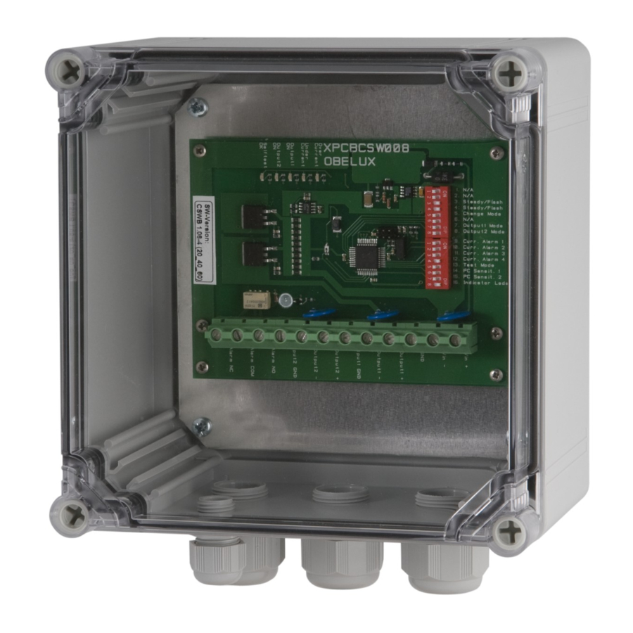
6 CONFIGURATION This chapter describes the configuration of the CSW-DCW board. The configuration is carried out by setting the 16 DIP switches on the CSW-DCW board. OFF position for a dip-switch is towards the left edge of the CSW-DCW board. -
Page 11: Flash Duration
6.4 Test mode DIP switch named TEST MODE selects the test mode. Test mode makes CSW-DCW system testing easier. Set the test-mode DIP switch to ON to enter test mode. In test mode output channel 1 can set ON from the Option 1 DIP. -
Page 12: Photocell Operation
CSW-DCW – Manual Obelux Oy, Kutomotie 6 B, 00380 Helsinki FINLAND 6.6 Photocell operation DIP switch named EXT/INT PHOTOCELL selects internal photocell. (off) Internal photocell is used. (on) External photocell is used. 6.7 Main/Spare operation DIP switch named MAIN/SPARE set the main/spare operation. -
Page 13: Configuration Example
Obelux Oy, Kutomotie 6 B, 00380 Helsinki FINLAND 6.10 Configuration example This example presents how to use Obelux CSW to control Obelux LI-10-DCW-F low intensity aviation obstacle lights in master/spare set-up with internal photocell. We have selected 400lux to be the threshold where low intensity lights are turned off. -
Page 14: Dip Switch Settings
CSW-DCW – Manual Obelux Oy, Kutomotie 6 B, 00380 Helsinki FINLAND 6.11 Dip Switch Settings DIP Switches 1 -> 3 Flashing sequence selection. Steady burning. All active channels. 60 flashes / minute 40 flashes / minute 20 flashes / minute BMVBW sequence: 1s on - 0.5s off - 1s on - 1.5s off. -
Page 15: Operation
The CSW-DCW can have a GPS receiver mounted on the printed circuit board that is used to synchronize all CSW-DCW flash sequences so that all CSW-DCW units flash their lights simultaneously all over the planet. Also, the CSW-DCW has an internal photocell on the board that can be used to switch off the lights at day time. -
Page 16: Alarms
When the CSW powered up the GPS alarm is triggered after 30min if GPS signal is not available. In normal operation GPS alarm is triggered if valid GPS time pulses are not received for 3 hours. CSW-DCW will also try to clear the error when GPS received. This way, GPS synchronization alarms caused by poor weather or similar will probably clear without any intervention. -
Page 17: On-Board Leds
CSW-DCW – Manual Obelux Oy, Kutomotie 6 B, 00380 Helsinki FINLAND 7.8 On-board LEDs This chapter describes the behaviour of the on-board message LEDs during start-up, normal operation and during alarms. Figure 3: Status LEDs +12V This LED indicates that internal 12V operating voltage is ok.
Need help?
Do you have a question about the CSW-DCW and is the answer not in the manual?
Questions and answers