Advertisement
Quick Links
Advertisement

Related Manuals for Superwinch H14W


Summary of Contents for Superwinch H14W
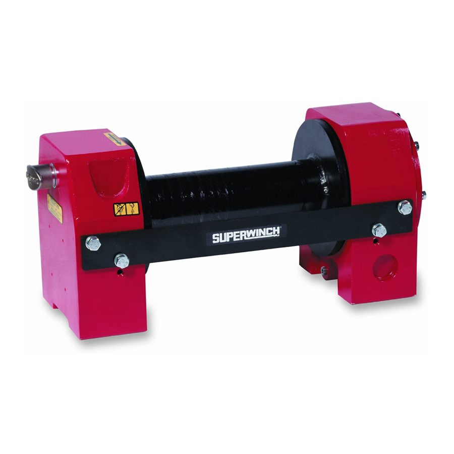
- Page 1 Fitting Instructions Kit Nos. 6760, 6760V, 7590 MECHANICALLY POWERED DRUM WINCHES...
- Page 3 COMMISSIONING AND USE SETTING & ADJUSTING THE SYSTEM FITTING THE ROPE TESTING & OPERATING INSTRUCTIONS RUNNING IN, MAINTENANCE & SERVICING ASSEMBLY DRAWINGS Superwinch Ltd., Abbey Rise, Whitchurch Road, Tavistock, Devon. Great Britain. PL19 9DR ( +44 (0)1822 614101 2 +44 (0)1822 615204 : support@superwinch.net...
- Page 4 GENERAL DESCRIPTION CAUTION : This calls attention to procedures These instructions outline fitting of an H14W drum winch which must be followed to avoid damage to and mechanical PTO onto a Land Rover Ninety, One- components.
-
Page 5: General Specification Data
GENERAL SPECIFICATION DATA WINCH Type ............... H14W (drum) Gear Reduction ............Worm wheel Wormbox ratio ............48 : 1 Drum ..............Fabricated steel mounted on maintenance free plain bearings Drum capacity ....ø 9mm (5/16”) ....77 (253’) ø10mm (3/8”) ....54 (177’) - Page 6 LUBRICANTS, FLUIDS & CAPACITIES PTO LUBRICANT OIL Fill PTO to level plug with the same oil as used in the vehicle transfer box (consult Land Rover workshop manuals for specifications). The PTO is fitted with two plugs, the upper one is the level plug, and the lower one is the drain plug.
- Page 7 WINCH / BUMPER BAR / ROLLER FAIRLEAD INSTALLATION OVERVIEW In this section we will fit the bumper / winch / roller fairlead to the vehicle. 110/127 4 cyl engined vehicles : It is recommended to fit heavy duty suspension springs on the front axle of the vehicle.
- Page 8 BUMP STOP SPACER INSTALLATION OVERVIEW In this section we will fit the Bump Stop Spacer. This will help the shafting to avoid hitting the axle when travelling off road. Identify the parts in the following kit : BUMP STOP SPACER KIT Part No.
- Page 9 STEERING DAMPER BRACKET INSTALLATION OVERVIEW In this section we will fit the Steering Damper Bracket. First though, identify the parts in the following assembly. PTO SHAFT KIT (For use on 90/110/127 TDi Defender V.I.N. 939976 onward) Part No. 70-90028V ITEM PART No.
- Page 10 PTO SHAFT KIT (For use on 90/110/127 Defender 4 cyl (inc. TDi) up to V.I.N. 939976) Part No. 70-90028 ITEM PART No. DESCRIPTION 4-32-1402512 BOLT M14 x 25 4-33-0809022 BOLT M8 x 90 4-33-0807022 BOLT M8 x 70 4-32-0805022 SET SCREW M8 x 50 4-32-0803512 SOCKET SET SCREW M8 x 35 4-33-0802022...
- Page 11 PTO SHAFT KIT(For use on V8 models) Part No. 70-90038 ITEM PART No. DESCRIPTION 4-32-1402512 SET SCREW M14 x 25 4-32-0805022 SET SCREW M8 x 50 4-32-0803512 SET SCREW M8 x 35 4-33-0802512 BOLT, M8 x 25 70-90027 COUPLING SHAFT ASSY 4-60-084003 RIVNUT M8 70-60063...
- Page 12 POWER TAKE OFF INSTALLATION OVERVIEW Here we will fit the Mechanical Power Take Off. Identify the parts in the following assemblies: P.T.O.FITTING KIT Part No. 7726 ITEM PART No. DESCRIPTION 4.50.0723 WASHER LOCK NUT CONTROL KNOB 4.33.1004512 BOLT M10 x 45 4.33.1004012 BOLT M10 x 40 4.51.1013...
- Page 13 P.T.O. Unit P.T.O. P.T.O. Operating knob Heelboard Drill one hole ø19mm (3/4") through the heelboard. Deburr hole and fit grommet (Item 119). Push operating shaft (Item 122) through the grommet (from inside the Fit key (Item 31) and Universal Joint (Item 32) to Power centre seat access hole).
- Page 14 SETTING & ADJUSTING THE PTO SETTING AND ADJUSTING THE PTO With the engine turned off, engage first gear and PTO (by pulling the knob towards the front of the vehicle), slide the torque adaptor supplied (Item 123) onto PTO output shaft. Using a 20mm A/F socket on the torque adaptor, check the torque reading.
- Page 15 SHAFTING INSTALLATION OVERVIEW Refer to previous sections for parts SHAFTING INSTALLATION All vehicles except TDi V.I.N. 939967 onwards : Assemble self-aligning bearing (100) to brackets (88 & 87) with M8 x 25 bolts (84) noting that the bearings slots in the brackets are offset towards the bearing. Position assembly under No.2 crossmember as shown, using the coupling shaft between the winch and the bearing.
- Page 16 Front (sump) mount bracket assembly on V.I.N. 939967 onwards vehicles Rear mount bracket assembly on V.I.N. 939967 onwards vehicles SHAFTING INSTALLATION 09-2...
- Page 17 NOTES ON EXHAUST CLEARANCE NOTES ON EXHAUST CLEARANCE Exhaust Modification Kit Part No. 8991 ITEM PART No. DESCRIPTION 8822 Rear Adaptor 8825 Front Tube Assembly 8889 Olive 8824 Clamp 4-33-0804522 Bolt M8 x 45 4-47-0823 Nut M8 4-51-0823 Spring Washer M8 4-50-0823 Plain Washer M8 On some vehicles, there is limited room between the...
- Page 18 approximately 260mm (10.23”) from the flange and compared with the angle of the 260mm section removed) square to the pipe as shown. Remove the rubber mounting and mounting bracket from the pipe bracket. Fit the hanging bracket to the new section of rear pipe. Place the modified rear pipe in position and twist the two Ensure that the new end of the rear pipe is square and sections of rear pipe as necessary to ensure correct...
- Page 19 FITTING THE ROPE FITTING THE ROPE Slacken off the Socket set screw on the winch drum and turn the drum so that the screw is uppermost. Unwind the rope and lay in a straight line on the ground. NEVER wind the rope onto the drum from a coil. Disengage the drum drive by pulling back the safety interlock handle and pulling the freespool handle towards the drum of the winch.
-
Page 20: Winching Procedure
TESTING AND OPERATING INSTRUCTIONS TESTING AND OPERATING INSTRUCTIONS WINCHING PROCEDURE OVERLOAD PROTECTION Wherever possible, point vehicle directly at load to obtain The overload device fitted to this P.T.O. is a fully even cable lay on drum. automatic torque limiter. When an overload condition is Put both vehicle gearbox lever and transfer box lever reached, an audible clicking will be heard coming from into neutral. -
Page 21: Maintenance
USE ONLY GRUB SCREWS SUPPLIED BY SUPERWINCH TO SECURE THE UNIVERSAL MAINTENANCE JOINTS. SUPERWINCH PART NUMBER - 245. Periodically check that all nuts and bolts are tight. FOR OTHER WINCH AND P.T.O SERVICING Check all grub screws in the universal joints are tight. -
Page 22: Assembly Drawings
ASSEMBLY DRAWINGS ASSEMBLY DRAWINGS 14-1... - Page 23 ASSEMBLY DRAWINGS 14-2...
- Page 24 ASSEMBLY DRAWINGS 14-3...
- Page 25 ASSEMBLY DRAWINGS 14-4...
- Page 26 ASSEMBLY DRAWINGS 14-5...
- Page 27 MECHANICAL P.T.O. Part No. 6440 ITEM PART No. DESCRIPTION 6447 SLIDING DOG 6443 DRIVE SHAFT 6453/4 6448 SELECTOR FORK 4.56.502413 ROLL PIN 6449 SELECTOR SHAFT 4.13.040080183 BALL BEARING 4.10.2528253 BUSH 6445 DRIVING SPROCKET 4.24.4053183 CIRCLIP 6459 GASKET 6441 CHAIN CASE 4.21.6423 'O' RING 6451...
- Page 28 A. Express warranties. Seller Warrants that the Superwinch is as described in the “Superwinch Owner’s Manual” provided herewith; no other express warranty is made in respect to the Superwinch. If any model or sample was shown to the Buyer, such model or sample was used for illustrative purposes only, and shall not be construed as a warranty that the Superwinch will conform to the sample or model.
- Page 29 This Manuals Part No. is : 9326 Issue No. 181197 Superwinch Ltd., Abbey Rise, Whitchurch Road, Tavistock, Devon. Great Britain. PL19 9DR ( +44 (0)1822 614101 2 +44 (0)1822 615204 : support@superwinch.net Superwinch Inc., Winch Drive, Putnam, Connecticut 06260 U.S.A.
Need help?
Do you have a question about the H14W and is the answer not in the manual?
Questions and answers