Table of Contents

Related Manuals for Ashida ADR141C


Summary of Contents for Ashida ADR141C
- Page 1 AD R 1 4 1 C / 2 4 1 C Page 1/86 Numerical Over Current / Earth Fault Protection Relay Type : ADR141C / 241C ASHIDA Electronics Pvt. Ltd. Ref: Manual / ADR141C / 241C Issue: 04D Date : 10.07.2014...
- Page 2 Ashida Electronics (p.) Ltd. Information in this manual is intended to be accurate and reliable. However Ashida assumes no responsibility for its use; nor for any infringements of rights of third parties, which may result from its use.
-
Page 3: Table Of Contents
Main Menu List Details Primary Current 8.3.3 8.3.3.1 To View – Primary Current General Setting 8.3.4 8.3.4.1 To Set – General Setting 8.3.4.2 To View – General Setting ASHIDA Electronics Pvt. Ltd. Ref: Manual / ADR141C / 241C Issue: 04D Date : 10.07.2014... - Page 4 Flow Chart – To View Trip Test Settings Flow Chart – To View Fault 1 (Fault 2 – Fault 8) Flow Chart – To View Events Log Settings ASHIDA Electronics Pvt. Ltd. Ref: Manual / ADR141C / 241C Issue: 04D Date : 10.07.2014...
- Page 5 10.7 Setting 10.7.1 General Setting 10.7.2 Bank Settings 10.8 Event List 11.0 Test Report Annexure – 1 11.1 Drawing for Test Setup. Revision Note 12.0 ASHIDA Electronics Pvt. Ltd. Ref: Manual / ADR141C / 241C Issue: 04D Date : 10.07.2014...
-
Page 6: Description
ADR141C / ADR241C are second generation Numerical 3OC + 1EF Over Current Relay. [The ADR241C is communicable Relay having RS485 Port. All the other features as per ADR141C Relay] It consist all the necessary protection and monitoring functions required for Normal feeder. It consists of High Speed Digital DSP Controller. -
Page 7: Protection Feature
Over Current & EF Element: The ADR141C is member of Ashida Numerical Relay family design for protection general feeder. The relay has one stage of IDMT/DMT setting and one stage of instantaneous setting. (Ip>, IP>>, 3Io>, 3Io>>). All major international IDMT curves are available. Range for first stage is 10% to 250% and 50% to 3000% for instantaneous stage for phase and 3Io. -
Page 8: Inverse Time Curve
K = Time multiplier setting or Time dial Setting Curve Type Description Standard Inverse_1 0.14 0.02 Standard Inverse_2 0.06 0.02 Very Inverse 13.5 Extremely inverse Long Time Inverse Define Time Inst 99.9 Sec ASHIDA Electronics Pvt. Ltd. Ref: Manual / ADR141C / 241C Issue: 04D Date : 10.07.2014... - Page 9 N U M E R I C AL O C / E F P R O T E C T I O N R E L AY AD R 1 4 1 C / 2 4 1 C Page 9/86 ASHIDA Electronics Pvt. Ltd. Ref: Manual / ADR141C / 241C Issue: 04D Date : 10.07.2014...
-
Page 10: Trip Circuit Supervision
Page 10/86 Trip circuit Supervision:- The ADR141C is having 2 separate digital opto-coupler status input which can be used to continuously monitor continuity of trip-circuit. The general scheme is as shown in fig. 4. Relay monitor Trip coil continuity through CB NO during close condition and through CB NC during Trip condition. -
Page 11: Cold Load Setting
PROTH contact 4 & 8 Trip Ckt Supervision Generate Error signal and remain in protection by assuming Fail Error 128 default setting value. change PROTH contact ASHIDA Electronics Pvt. Ltd. Ref: Manual / ADR141C / 241C Issue: 04D Date : 10.07.2014... -
Page 12: Technical Details
0.1 – 99.9 Sec in steps of 0.1Sec. : IP>> Settings 50% – 3000% in steps of 50% : IP>> Delay 0 – 2.00 Sec in steps of 0.01Sec. ASHIDA Electronics Pvt. Ltd. Ref: Manual / ADR141C / 241C Issue: 04D Date : 10.07.2014... - Page 13 : Green LED indicates Output TRIP relay contact closer (SR) Type XIX. Drawing References : For Typical External connection - ADV02702 : For Cabinet Type - MAC01501 (CSF) ASHIDA Electronics Pvt. Ltd. Ref: Manual / ADR141C / 241C Issue: 04D Date : 10.07.2014...
-
Page 14: Type Test Detail
: Polarity : + ve and – Ve : Nos. of impulses : 3 positive and 3 negative impulse : Duration between Impulses : 5 sec. ASHIDA Electronics Pvt. Ltd. Ref: Manual / ADR141C / 241C Issue: 04D Date : 10.07.2014... - Page 15 : In single axis sine sweep in Y-axis - sweep (@a sweep rate of 1 octave/minute) vibration in the frequency range (5-40 Hz) at amplitude of 1.5mm or 0.5gn (whichever is less) ASHIDA Electronics Pvt. Ltd. Ref: Manual / ADR141C / 241C Issue: 04D Date : 10.07.2014...
-
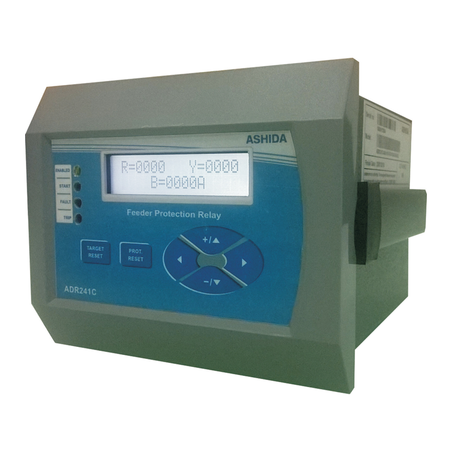
Page 18: Front Panel And Control
1 key provided for Hardware reset. This key will be interlocked with LED Reset / EDIT. Navigation 4 keys provided for navigation through different display menu and to do setting ASHIDA Electronics Pvt. Ltd. Ref: Manual / ADR141C / 241C Issue: 04D Date : 10.07.2014... -
Page 19: User's Interface
‘HW RESET’ key is never require in normal operation, It is in series with ‘LED RESET/EDIT’ key, When both keys are pressed simultaneously it reset total hardware of relay. This normally is required during firmware update of relay. ASHIDA Electronics Pvt. Ltd. Ref: Manual / ADR141C / 241C Issue: 04D Date : 10.07.2014... -
Page 20: Led's
Password 8.2.1 Password Entry and changing the password To enter password in all ADR141C refer following steps (User can go to this screen by pressing HW RESET + LED RESET/EDIT Simultaneously This is default window showing the actual Primary Load... - Page 21 Mode for Save to ‘’General Settings’ This window will flash for moment The control will return to the main menu → General Settings ← ASHIDA Electronics Pvt. Ltd. Ref: Manual / ADR141C / 241C Issue: 04D Date : 10.07.2014...
-
Page 22: Clear Password
This will Reset password to ‘0’ (Zero). Ashida Digital OC/EF Relay ADR141C – 01.20 Unit ID = 0001 Fault Memories & Password clear R= 0000 Y = 0000 B = 0000A ASHIDA Electronics Pvt. Ltd. Ref: Manual / ADR141C / 241C Issue: 04D Date : 10.07.2014... -
Page 23: Menus
Then the control will go automatically to next window. This window will flash momentarily showing the following ADR141C - Ver. 01.20 Relay Type : ADR141C Software Version : V01.20 Unit ID : 0001 Unit ID = 0001 Then the control will go automatically to default window... -
Page 24: 8.3.2.1 Main Menu List Details
3Io>> Enable, 3Io>> Multiply, IP Curve, 3Io Curve, IP>> Delay, 3Io>> Delay, IP> C6 Delay, 3Io> C6 Delay. Press the down arrow key ( - / ) the relay will display as follows. ASHIDA Electronics Pvt. Ltd. Ref: Manual / ADR141C / 241C Issue: 04D Date : 10.07.2014... - Page 25 That is Trip Flags, Instantaneous and Phase primary Current, Trip Counter (TC), Fault Date & Time. Press the down arrow key (- / ) the relay will display as follows. ASHIDA Electronics Pvt. Ltd. Ref: Manual / ADR141C / 241C Issue: 04D Date : 10.07.2014...
- Page 26 This menu is to view the Status that is Digital Input, Trip Status Ckt., Ckt Breaker and S/W & H/W versions. Press the down arrow key (- / ) the relay will display as follows. ASHIDA Electronics Pvt. Ltd. Ref: Manual / ADR141C / 241C Issue: 04D Date : 10.07.2014...
-
Page 27: Primary Current
This window will show Primary load current of 3Io. 3Io = 0000A Press the right arrow key ( ) the relay will display main menu Pri. Current ASHIDA Electronics Pvt. Ltd. Ref: Manual / ADR141C / 241C Issue: 04D Date : 10.07.2014... -
Page 28: General Setting
1 while selecting 1 Amp and between Com. and 5 while selecting 5Amp. Press the left arrow key ( ) the relay will display as follows ASHIDA Electronics Pvt. Ltd. Ref: Manual / ADR141C / 241C Issue: 04D Date : 10.07.2014... - Page 29 1200 to 57600. (i.e. 1200, 2400, 9600, 19200, 38400 and 57600) ( Only for ADR241C ) Press the left arrow key ( ) the relay will display as follows. ASHIDA Electronics Pvt. Ltd. Ref: Manual / ADR141C / 241C Issue: 04D Date : 10.07.2014...
- Page 30 Reset or leave key pad untouched for 100 sec. This window will flash for moment The control will return to the main menu General Setting ASHIDA Electronics Pvt. Ltd. Ref: Manual / ADR141C / 241C Issue: 04D Date : 10.07.2014...
-
Page 31: To View - General Setting
This window will show General Setting done previously. Frequency = 50Hz Press the right arrow key ( ) the relay will display Main Menu. General Setting ASHIDA Electronics Pvt. Ltd. Ref: Manual / ADR141C / 241C Issue: 04D Date : 10.07.2014... -
Page 32: Relay Setting
NO. If set YES then IP>> setting is enabled and if set NO then it will be disabled Press the left arrow key ( ) the relay will display as follows. ASHIDA Electronics Pvt. Ltd. Ref: Manual / ADR141C / 241C Issue: 04D Date : 10.07.2014... - Page 33 In similar manner any desired curve can be selected as 001 to 006 correspond respectively with C1 to C6. Press the left arrow key ( ) the relay will display as follows. ASHIDA Electronics Pvt. Ltd. Ref: Manual / ADR141C / 241C Issue: 04D Date : 10.07.2014...
- Page 34 Note: If changes made are not to be saved press LED Reset or leave key pad untouched for 100Sec. This window will flash for moment The control will return to the main menu Relay Setting ASHIDA Electronics Pvt. Ltd. Ref: Manual / ADR141C / 241C Issue: 04D Date : 10.07.2014...
-
Page 35: To View - Relay Setting
IP> C6 Delay = 04.0 3Io> C6 Delay = 00.0 Press the right arrow key ( ) the relay will display the main menu. Relay Setting ASHIDA Electronics Pvt. Ltd. Ref: Manual / ADR141C / 241C Issue: 04D Date : 10.07.2014... -
Page 36: Cold Load Settings
( - / ) the IP> can be set in Range 10 250% in steps of Range 10 – 250% 001% Press the left arrow key ( ) the relay will display as follows. ASHIDA Electronics Pvt. Ltd. Ref: Manual / ADR141C / 241C Issue: 04D Date : 10.07.2014... - Page 37 NO. If set YES then 3Io>> setting is enabled and if set NO then it will be disabled Press the left arrow key ( ) the relay will display as follows. ASHIDA Electronics Pvt. Ltd. Ref: Manual / ADR141C / 241C Issue: 04D Date : 10.07.2014...
- Page 38 Range 0.1 – 99.9s in between 0.1 – 99.9s in steps of 00.1s Press the left arrow key ( ) the relay will display as follows. ASHIDA Electronics Pvt. Ltd. Ref: Manual / ADR141C / 241C Issue: 04D Date : 10.07.2014...
- Page 39 Note: If changes made are not to be saved press LED Reset or leave key pad untouched for 100Sec. This window will flash for moment The control will return to the main menu Relay Setting ASHIDA Electronics Pvt. Ltd. Ref: Manual / ADR141C / 241C Issue: 04D Date : 10.07.2014...
-
Page 40: 8.3.6.2 To View - Cold Load Setting
IP> C6 Delay = 00.5 Press the right arrow key ( ) the relay will display the main 3Io> C6Delay = 01.0 menu. Cold Load ASHIDA Electronics Pvt. Ltd. Ref: Manual / ADR141C / 241C Issue: 04D Date : 10.07.2014... -
Page 41: Relay/Led Configuration
Internal Derived EF ( 3Io ) IDMT/DMT Over Current Pkp. R>> Pkp R Phase Inst. Over Current Pkp. Y>> Pkp Y Phase Inst. Over Current Pkp. ASHIDA Electronics Pvt. Ltd. Ref: Manual / ADR141C / 241C Issue: 04D Date : 10.07.2014... - Page 42 Refer following table for some equivalent Binary, Hex and Decimal values. Binary Value Hex decimal Values Decimal Values 0000 0001 0010 0011 0100 0101 0110 0111 1000 1001 1010 1011 1100 1101 1110 1111 ASHIDA Electronics Pvt. Ltd. Ref: Manual / ADR141C / 241C Issue: 04D Date : 10.07.2014...
- Page 43 2. If you want to set Relay 4 for BF (SR), then you set bit as follow. Bit Posit. Bit for A Bit for B L2 Green A L2 Green B i.e. RL2 A = 0200 RL2 B = 0000 ASHIDA Electronics Pvt. Ltd. Ref: Manual / ADR141C / 241C Issue: 04D Date : 10.07.2014...
-
Page 44: To Set - Relay/Led Configuration
L3 Green B = 0000 L3 Red A = 01FF L3 Red B = 0200 L4 Green A = 01FF L4 Green B = 0000 ASHIDA Electronics Pvt. Ltd. Ref: Manual / ADR141C / 241C Issue: 04D Date : 10.07.2014... - Page 45 This window shows the Relay/LED configuration. That is RL3 A = 01FF RL3 A Press the left arrow key ( ) the relay will display as follows. ASHIDA Electronics Pvt. Ltd. Ref: Manual / ADR141C / 241C Issue: 04D Date : 10.07.2014...
- Page 46 This window shows the Relay/LED configuration. That is L2 L2 Green A = 0000 Green A Press the left arrow key ( ) the relay will display as follows. ASHIDA Electronics Pvt. Ltd. Ref: Manual / ADR141C / 241C Issue: 04D Date : 10.07.2014...
- Page 47 This window shows the Relay/LED configuration. That is L4 L4 Green B = 0000 Green B. Press the left arrow key ( ) the relay will display as follows. ASHIDA Electronics Pvt. Ltd. Ref: Manual / ADR141C / 241C Issue: 04D Date : 10.07.2014...
- Page 48 Reset or leave key pad untouched for 100Sec. This window will flash for moment The control will return to the main menu Relay/ LED Config. ASHIDA Electronics Pvt. Ltd. Ref: Manual / ADR141C / 241C Issue: 04D Date : 10.07.2014...
-
Page 49: To View - Relay/Led Configuration
This window will show Relay config. setting done L1 Red A = 8000 previously. L1 Red B = 01FF Press the right arrow key ( ) the relay will display as follows. ASHIDA Electronics Pvt. Ltd. Ref: Manual / ADR141C / 241C Issue: 04D Date : 10.07.2014... - Page 50 L4 Red A = 8000 previously. L4 Red B = 01FF Press the right arrow key ( ) the relay will display the main menu. Relay/ LED Config. ASHIDA Electronics Pvt. Ltd. Ref: Manual / ADR141C / 241C Issue: 04D Date : 10.07.2014...
-
Page 51: Trip Test
This window will show date and time of fault. 20/06/13 16:45:50:603 Press the right arrow key ( ) the relay will display main menu i.e. Fault 1. Fault 1 ASHIDA Electronics Pvt. Ltd. Ref: Manual / ADR141C / 241C Issue: 04D Date : 10.07.2014... -
Page 52: Fault 1
Press the right arrow key ( ) the relay will display main menu. Fault 1 Note : Fault 2 to Fault 8 can be viewed as above ASHIDA Electronics Pvt. Ltd. Ref: Manual / ADR141C / 241C Issue: 04D Date : 10.07.2014... -
Page 53: Events Log
This window will show Error Code detected by self Error Code : 0000 supervision function of Relay Press the right arrow key ( ) the relay will display main menu. Error Log ASHIDA Electronics Pvt. Ltd. Ref: Manual / ADR141C / 241C Issue: 04D Date : 10.07.2014... -
Page 54: Status
This window will shows the software and hardware version of S/W V: 01.20 relay H/W V: 01.01 Press the right arrow key ( ) the relay will display the main menu. Status ASHIDA Electronics Pvt. Ltd. Ref: Manual / ADR141C / 241C Issue: 04D Date : 10.07.2014... -
Page 55: Date Time Setting
( - / ) Month can be set. The setting range is from 1-12 in Range 1 – 12 steps of 1. Press the left arrow key ( ) the relay will display as follows. ASHIDA Electronics Pvt. Ltd. Ref: Manual / ADR141C / 241C Issue: 04D Date : 10.07.2014... -
Page 56: To View - Date Time Setting
This window shows the Date and Time Time: 16: 40: 57 Date: 19/06/13 Press the right arrow key ( ) the relay will display the main menu. Date / Time ASHIDA Electronics Pvt. Ltd. Ref: Manual / ADR141C / 241C Issue: 04D Date : 10.07.2014... -
Page 57: Secondary Current
This window will show secondary load current of 3Io. 3Io = 00.00 Press the right arrow key ( ) the relay will display as follows. Sec. Current ASHIDA Electronics Pvt. Ltd. Ref: Manual / ADR141C / 241C Issue: 04D Date : 10.07.2014... -
Page 58: Flow Chart
Flow Chart – To View Primary Current R = 0000 Y = 0000 Primary Current B = 0000A R = 0000 Y = 0000 B = 0000A 3Io = 0000A ASHIDA Electronics Pvt. Ltd. Ref: Manual / ADR141C / 241C Issue: 04D Date : 10.07.2014... -
Page 59: Flow Chart - To Set / View General Settings
NOTE : The Baud Rated setting is only for ADR241C. Baud Rate = 57600 Frequency = 50Hz Range 1200 - 57600 Range 50Hz – 60Hz Save Settings? Mode for Save ASHIDA Electronics Pvt. Ltd. Ref: Manual / ADR141C / 241C Issue: 04D Date : 10.07.2014... -
Page 60: Flow Chart - To Set / View Relay Settings
3Io>> Delay = 0.01 Range 0.1 – 99.9s Range 0 – 2.00s Save Settings ? 3Io>C6 Del = 04.1 Mode for Save Range 0.1 – 99.9s ASHIDA Electronics Pvt. Ltd. Ref: Manual / ADR141C / 241C Issue: 04D Date : 10.07.2014... -
Page 61: Flow Chart - To Set / View Cold Load Settings
Ip> C6 Del = 00.5 Range 0 – 2.00S Range 0.1 – 99.9S 3IO> C6 Del = 00.5 Save setting? Range 0.1 – 99.9S Mode for Save ASHIDA Electronics Pvt. Ltd. Ref: Manual / ADR141C / 241C Issue: 04D Date : 10.07.2014... -
Page 62: Flow Chart - To Set / View Relay/Leds Settings
L4 Green A = 01FF L4 Green B = 0000 Save Setting? MODE for Save L4 Red A = 0000 L4 Red B = 0000 ASHIDA Electronics Pvt. Ltd. Ref: Manual / ADR141C / 241C Issue: 04D Date : 10.07.2014... -
Page 63: Flow Chart - To View Trip Test Settings
Flow Chart – To View – TRIP TEST Trip Test I>>: I>: T R=0000 Y=0000 B=0000A 3Io= 0000A Trip Count : 0000 19/06/2013 16:53:21.058 Fault 1 ASHIDA Electronics Pvt. Ltd. Ref: Manual / ADR141C / 241C Issue: 04D Date : 10.07.2014... -
Page 64: Flow Chart - To View Fault 1 (Fault 2 - Fault 8)
Test F 19/06/13 Test F 19/06/13 06 12:37:44.076 05 12:37:44.076 Test F 19/06/13 04 12:37:44.076 Note : Events 2 to Events 16 can be viewed respectively. ASHIDA Electronics Pvt. Ltd. Ref: Manual / ADR141C / 241C Issue: 04D Date : 10.07.2014... -
Page 65: Flow Chart - To View Error Log Settings
Flow Chart – To View Status Settings Status CB NO:OFF Trip Ckt : Healthy S/W V: 01.20 CB NC:OFF Ckt Brker :? H/W V: 01.01 ASHIDA Electronics Pvt. Ltd. Ref: Manual / ADR141C / 241C Issue: 04D Date : 10.07.2014... -
Page 66: Flow Chart - To Set / View Date/Time Settings
Range 0-59 SET Date = 003 Range 1-31 SET Month : 004 Range 1-12 SET Year = 009 Range 00-99 Save Settings? Mode for Save ASHIDA Electronics Pvt. Ltd. Ref: Manual / ADR141C / 241C Issue: 04D Date : 10.07.2014... -
Page 67: Flow Chart - To View Secondary Current
Page 67/86 9.12 Flow Chart – To View – Secondary Current Sec. Current R = 00.00 Y = 00.00 B = 0000 3Io = 00.00 ASHIDA Electronics Pvt. Ltd. Ref: Manual / ADR141C / 241C Issue: 04D Date : 10.07.2014... -
Page 68: Communication - Only For Adr241C Relay
To read this fault information communication port are provided i.e. RS485 at rear. The relay use 3 wire communication port. (RX, TX and GND) hand shaking signal are not used such RTS, CTS, DSR DTR. ASHIDA Electronics Pvt. Ltd. Ref: Manual / ADR141C / 241C Issue: 04D Date : 10.07.2014... -
Page 69: General Questions
10.2.7 Why RS232 to RS485 ISOLATED CONVERTOR is used? Generally PC is provided with RS232 port, to connect Relay with standard PC we need RS232 to RS485 Isolated Convertor. ASHIDA Electronics Pvt. Ltd. Ref: Manual / ADR141C / 241C Issue: 04D Date : 10.07.2014... -
Page 70: Physical Connection And Link Layer
RS485 communication port Electrical Connection provided at back of Relay RS485 PORT Rx- are Input to relay RX + Tx- are output from relay RX - TX - TX + D9 Male Fig. 10.2 ASHIDA Electronics Pvt. Ltd. Ref: Manual / ADR141C / 241C Issue: 04D Date : 10.07.2014... -
Page 71: Relay Talk System For Downloading The Data
For success communication setting of relay should match with software settings. In relay Talk software there are numbers of settings. Here we have shown only essential screens for ADR241C relay. To check communication setting click configuration button. ASHIDA Electronics Pvt. Ltd. Ref: Manual / ADR141C / 241C Issue: 04D Date : 10.07.2014... - Page 72 Communication settings Fig. 10.4 Now check communication setting. Adjust Proper COM Port Settings Adjust Proper Baud Rate Setting There should be no handshaking Fig. 10.5 ASHIDA Electronics Pvt. Ltd. Ref: Manual / ADR141C / 241C Issue: 04D Date : 10.07.2014...
- Page 73 & finally Press This will return to main screen. Default IDs settings Relay ID Here we set the Default ID of the Relay. Fig. 10.6 ASHIDA Electronics Pvt. Ltd. Ref: Manual / ADR141C / 241C Issue: 04D Date : 10.07.2014...
- Page 74 ID setting as shown in figure. 3. Check unit ID, Parity, Com Port and Baud rate of ADR241C relay it should match to the configuration of the software. ASHIDA Electronics Pvt. Ltd. Ref: Manual / ADR141C / 241C Issue: 04D Date : 10.07.2014...
-
Page 75: Adr241C Ied Main Screen
This is used to view the parameters of current and voltage List of Disturbance This is used to view the last 5 faults saved in the relay with Recorder fault number. ASHIDA Electronics Pvt. Ltd. Ref: Manual / ADR141C / 241C Issue: 04D Date : 10.07.2014... -
Page 76: 10.5.1 Parameter Display
Fig. 10.9 10.5.2 Physical/Logical Status Display (IEDs Din) These are physical/logical status (IED Dins), displayed along with there online status. Fig. 10.10 ASHIDA Electronics Pvt. Ltd. Ref: Manual / ADR141C / 241C Issue: 04D Date : 10.07.2014... -
Page 77: 10.5.3 Control Operation
This window is used to operate the controls Fig. 10.12 Fig. 10.13 10.5.4 Private Setting These settings for IEDs are displayed along with their current values and expected values. Fig. 10.14 ASHIDA Electronics Pvt. Ltd. Ref: Manual / ADR141C / 241C Issue: 04D Date : 10.07.2014... -
Page 78: History Fault
To refresh all windows and parameters Clear Fault display To clear the screen Save Fault data To Save the Fault data Close To close the History fault window ASHIDA Electronics Pvt. Ltd. Ref: Manual / ADR141C / 241C Issue: 04D Date : 10.07.2014... -
Page 79: Setting
General Settings and Bank Settings. 10.7.1 General Settings This window is to view and edit the parameters in general settings of the relay. Fig. 10.16 ASHIDA Electronics Pvt. Ltd. Ref: Manual / ADR141C / 241C Issue: 04D Date : 10.07.2014... -
Page 80: Bank Settings
AD R 1 4 1 C / 2 4 1 C Page 80/86 10.7.2 Bank Settings This window is to view and edit the parameters in Bank settings of the relay. Fig. 10.17 ASHIDA Electronics Pvt. Ltd. Ref: Manual / ADR141C / 241C Issue: 04D Date : 10.07.2014... -
Page 81: Event List
This window shows the all events generated in the relay. The following picture shows the auxiliary status and their event list. Fig. 10.18 Fig. 10.19 ASHIDA Electronics Pvt. Ltd. Ref: Manual / ADR141C / 241C Issue: 04D Date : 10.07.2014... - Page 82 When the relay is not in Trip mode following events are shown. 1. General start/pick up OFF 2. General Trip OFF 3. Test event OFF ASHIDA Electronics Pvt. Ltd. Ref: Manual / ADR141C / 241C Issue: 04D Date : 10.07.2014...
-
Page 83: Test Report Annexure
Keep Trip at 250% & TMS at X1.0 Phase - HF % 1000% (Tolerance 10A – 11A) R (Amps) Y (Amps) B (Amps) 3IO (Amps) ASHIDA Electronics Pvt. Ltd. Ref: Manual / ADR141C / 241C Issue: 04D Date : 10.07.2014... - Page 84 Insulation test: __________________MΩ @ 1000VDC. H.V. Test: @ 2000VAC between all Terminals and body for 60 Sec. _____________. RS 485 Communication:______________________ 10. Conclusion: _________________________________________________________. Tested By Checked By (QC) ASHIDA Electronics Pvt. Ltd. Ref: Manual / ADR141C / 241C Issue: 04D Date : 10.07.2014...
-
Page 86: Revision Note
22.03.2011 IDMT Graph modified. 03.10.2012 Software Version Changed 19.06.2013 Software Version Changed • 10.07.2014 Software Version Changed 01.20 • Communication modified from 4wires to 2wires. ASHIDA Electronics Pvt. Ltd. Ref: Manual / ADR141C / 241C Issue: 04D Date : 10.07.2014...
Need help?
Do you have a question about the ADR141C and is the answer not in the manual?
Questions and answers