
Related Manuals for Ashida ADR241B


Summary of Contents for Ashida ADR241B
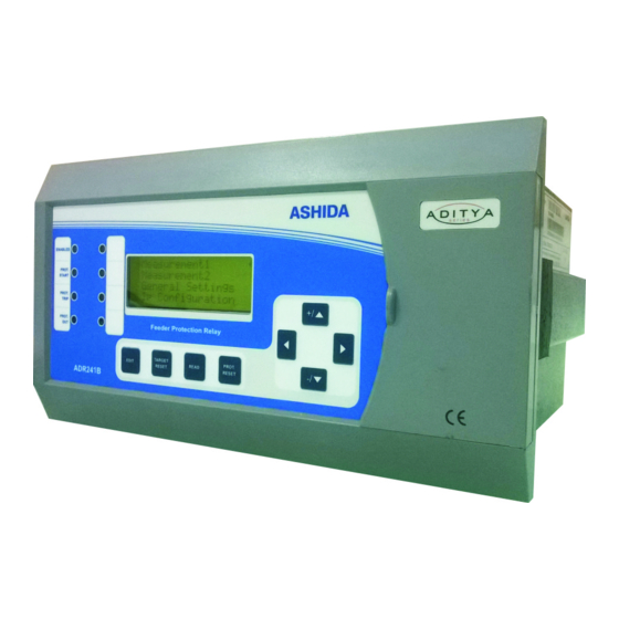
- Page 1 ADR241B ADR241B (Draw Out Version) Feeder Protection Relay Instruction Manual Software Version : V3.xx Hardware Version : V1.xx Doc ID : ADR241B-DO_IM_01 Ref ID : ADR241B/IM/TP Rev No. : 06 Page No. : 1 of 272...
- Page 2 ADR241B Preface The ADR241B Feeder Management Relay Instruction Manual describes common aspects of feeder protection application and use of product. It includes the necessary information to safety, install, set, test, and operate the relay functionality. The instruction manual can be used by power engineers and other experienced protective relaying applications.
- Page 3 Qualified personnel are individuals who • Are familiar with the installation, commissioning, operation of the equipment and of the system to which it is being connected. Doc ID : ADR241B-DO_IM_01 Ref ID : ADR241B/IM/SGI Rev No. : 06 Page No.
- Page 4 However, the manual cannot cover all conceivable circumstances or include detailed information on all topics. In the event of questions or specific problems, do not take any action without proper authorization. Contact the appropriate person of Ashida Technical / Sales office and request the necessary information.
- Page 5 If working in an area of restricted space, such as a cubicle, where there is a risk of electric shock due to accidental touching of terminals which do not comply with IP20 rating, then a suitable protective barrier should be provided. Doc ID : ADR241B-DO_IM_01 Ref ID : ADR241B/IM/SGI Rev No.
- Page 6 External resistors, including voltage dependent resistors (VDRs) Where external resistors, including voltage dependent resistors (VDRs), are fitted to the equipment, these may present a risk of electric shock or burns, if touched. Doc ID : ADR241B-DO_IM_01 Ref ID : ADR241B/IM/SGI Rev No.
- Page 7 To avoid electric shock or energy hazards, after completely isolating the supplies to the equipment (both poles of any dc supply), the capacitors should be safely discharged via the external terminals prior to decommissioning. Doc ID : ADR241B-DO_IM_01 Ref ID : ADR241B/IM/SGI Rev No.
- Page 8 IEC 60529 with the classification of degree of protection IP52 (dust and splashing water protected). Doc ID : ADR241B-DO_IM_01 Ref ID : ADR241B/IM/SGI Rev No.
- Page 9 Pollution Degree 2 Compliance is demonstrated by reference to safety standards. Altitude Operation up to 2000m IEC 60255-27:2005 EN 60255-27: 2005 CE MARKING Directives: Compliance demonstrated by reference to safety standards Doc ID : ADR241B-DO_IM_01 Ref ID : ADR241B/IM/SGI Rev No. : 06 Page No. : 9 of 272...
- Page 10 Page intentionally Left Blank...
- Page 11 Current Transformers 2.3.11 Output Relay Connections 2.3.12 USB Connection Mechanical Dimensions and Electrical Connection 2.4.1 Mechanical Dimensions ADR241B without IP cover 2.4.2 Mechanical Dimensions ADR241B with IP cover Doc ID : ADR241B-DO_IM_01 Ref ID : ADR241B/IM/ToC Rev No. : 06 Page No.
- Page 12 ADR241B 2.4.3 Back Terminal connection diagram for ADR241B 2.4.4 Electrical wiring connection diagram for ADR241B Section 3 : PC SOFTWARE INFORMATION Sr. No. Description Page No. PC SOFTWARE INFORMATION Overview 3.1.1 RTV2 Software Features Installation and Setup 3.2.1 System Requirement 3.2.2...
- Page 13 Phase Over current Element (50/51) Ground Over current Element (50N/51N) 4.5.1 Ground Over current (50/N/51N) 4.5.2 Residual Over current (50N/51N) Negative Sequence Over current (46) Doc ID : ADR241B-DO_IM_01 Ref ID : ADR241B/IM/ToC Rev No. : 06 Page No. : 13 of 272...
- Page 14 Thermal Overload Under Current. 6.10 Inrush Blocking 6.11 Date and Time setting 6.12 Reclosing 6.13 C12–User Define Curve Setting 6.14 IP Configuration Setting Doc ID : ADR241B-DO_IM_01 Ref ID : ADR241B/IM/ToC Rev No. : 06 Page No. : 14 of 272...
- Page 15 8.1.1 LCD Display 8.1.2 Touch Keys 8.1.3 LEDs 8.1.4 RS485 Port 8.1.5 USB Port Password 8.2.1 Editing Password and saving the settings. Doc ID : ADR241B-DO_IM_01 Ref ID : ADR241B/IM/ToC Rev No. : 06 Page No. : 15 of 272...
- Page 16 To View – UNDER CURRENT Settings 8.3.13 INRUSH BLOCKING SETTINGS 8.3.13.1 To Set – INRUSH BLOCKING Settings 8.3.13.2 To View – INRUSH BLOCKING Settings Doc ID : ADR241B-DO_IM_01 Ref ID : ADR241B/IM/ToC Rev No. : 06 Page No. : 16 of 272...
- Page 17 To View – Phase Overcurrent Flow Chart – Ground Overcurrent 9.5.1 To Set – Ground Overcurrent 9.5.2 To View – Ground Overcurrent Doc ID : ADR241B-DO_IM_01 Ref ID : ADR241B/IM/ToC Rev No. : 06 Page No. : 17 of 272...
- Page 18 9.18.1 To Set – C12 – User Define 9.18.2 To View – C12 – User Define 9.19 To View – CB Trip Doc ID : ADR241B-DO_IM_01 Ref ID : ADR241B/IM/ToC Rev No. : 06 Page No. : 18 of 272...
- Page 19 Checking of External Circuitry 11.3 Check Relay Setting 11.4 Relay Testing 11.5 Pick up and Trip Test: 11.6 Testing of Binary Output 11.7 LED Test Doc ID : ADR241B-DO_IM_01 Ref ID : ADR241B/IM/ToC Rev No. : 06 Page No. : 19 of 272...
- Page 20 Page intentionally Left Blank...
- Page 21 ADR241B Section 1 Introduction and Specifications Doc ID : ADR241B-DO_IM_01 Ref ID : ADR241B/IM/I&S Rev No. : 06 Page No. : 21 of 272...
-
Page 22: Table Of Contents
ADR241B Contents INTRODUCTION AND SPECIFICATIONS Overview Features Technical Specifications Typical Tests Information Doc ID : ADR241B-DO_IM_01 Ref ID : ADR241B/IM/I&S Rev No. : 06 Page No. : 22 of 272... -
Page 23: Introduction And Specifications
Overview ASHIDA has designed economical & reliable Multifunction ADR241B Protection & Control System. The simple and compact construction of ADITYA series ADR241B relay provides integrated Protection, Control and Monitoring functions for Over head Transmission Lines, Underground cables, and Distributed Feeders. - Page 24 Setting Editor. • Programmable scheme logic Editor. • Settings upload / download. • Offline Settings Editor. • Online Measurement. • Disturbance analysis. Doc ID : ADR241B-DO_IM_01 Ref ID : ADR241B/IM/I&S Rev No. : 06 Page No. : 24 of 272...
- Page 25 Underground cable & feeder protection. Relay designed with fast and selective tripping ensures the stability and availability of electrical power system. ADR241B relay apply for protection, control & monitoring of radial and ring main feeder to achieve sensitivity and selectivity on phase and ground faults.
- Page 26 ADR241B Apply for Transformer Feeder Protection Fig1: Radial Feeder application Apply for Parallel Transformer Feeder Protection Fig2: Ring Main Feeder application Doc ID : ADR241B-DO_IM_01 Ref ID : ADR241B/IM/I&S Rev No. : 06 Page No. : 26 of 272...
-
Page 27: Technical Specifications
ADR241B Technical Specifications AC Measuring Input: Measurement Accuracy Typical ± 2% at In for Phase and EF Nominal Frequency Range 50/60 Hz (Selectable in ADR241B Menu) For Current Inputs III. Frequency measurement 45 Hz – 65 Hz range Phase rotation... - Page 28 Note “ * “ indicates Reference Condition that is Fault current 2 time above rated value. III. Residual Over current: For operating Pick-up 1.05 x Setting ±5% Value Drop –off 0.95 x Setting ±5% Doc ID : ADR241B-DO_IM_01 Ref ID : ADR241B/IM/I&S Rev No. : 06 Page No. : 28 of 272...
- Page 29 50ms whichever is greater DT Operation ±5% or 50ms whichever is greater * * Reference Condition Fault current 2 time above rated value Doc ID : ADR241B-DO_IM_01 Ref ID : ADR241B/IM/I&S Rev No. : 06 Page No. : 29 of 272...
- Page 30 MAC01966 I. Drawing References : For Cabinet Type (With IP Cover) MAC01984 : For Back Connections APR09803 : For Electrical connection APR09903 Doc ID : ADR241B-DO_IM_01 Ref ID : ADR241B/IM/I&S Rev No. : 06 Page No. : 30 of 272...
-
Page 31: Typical Tests Information
(ed3) Modulation 80% AM @ 1 KHz Radio Frequency Field Dwell Time 2.85 Sec. EUT Condition Energized Spot Frequency 27, 68 MHz Doc ID : ADR241B-DO_IM_01 Ref ID : ADR241B/IM/I&S Rev No. : 06 Page No. : 31 of 272... - Page 32 Cold test : IEC-60068-2-1 Dry heat test : IEC-60068-2-2 III. Damp heat test, steady state : IEC-60068-2-78 Change of Temperature : IEC-60068-2-14 Doc ID : ADR241B-DO_IM_01 Ref ID : ADR241B/IM/I&S Rev No. : 06 Page No. : 32 of 272...
- Page 33 : Sweep 1/Axis (@a sweep rate of 1 octave/minute) vibration in the frequency range (5-35 Hz) at displacement X-axis: 7.5mm, Y-axis: 3.5mm amplitude of 3.5mm with acceleration of X-axis: 2gn, Y-axis: 1gn. Doc ID : ADR241B-DO_IM_01 Ref ID : ADR241B/IM/I&S Rev No. : 06 Page No.
- Page 34 Page intentionally Left Blank...
- Page 35 ADR241B Section 2 Installation and Procedure Doc ID : ADR241B-DO_IM_01 Ref ID : ADR241B/IM/I&P Rev No. : 06 Page No. : 35 of 272...
- Page 36 2.3.11 Output Relay Connections 2.3.12 USB Connection Mechanical Dimensions and Electrical Connection 2.4.1 Mechanical Dimensions ADR241B without IP cover 2.4.2 Mechanical Dimensions ADR241B with IP cover 2.4.3 Back Terminal connection diagram for ADR241B 2.4.4 Electrical wiring connection diagram for ADR241B Doc ID : ADR241B-DO_IM_01 Ref ID : ADR241B/IM/I&P...
-
Page 37: Instalation And Procedure
User should carefully plan relay placement, cable connections, and relay communication. This section contains drawings of typical ac and dc connections to the ADR241B. Use these drawings as a starting point for planning your particular relay application. -
Page 38: Storing The Goods
Installation Procedure 2.3.1 Safe Mounting ADR241B supports flush panel mounting and can be mounted into panels using M4 X 12 screws. The Protective cover and M4 X 25 screws (optional) are supplied along with the relay. NOTE: The protective cover is optional for IP54 compliance and will be provided with relay as per customer requirement. - Page 39 After inserting the Relay in the Panel fasten the relay to the Panel as shown below. Figure 2: Fastening Relay to the panel Caution: Always use M4x12 screws for Relay fitting. Doc ID : ADR241B-DO_IM_01 Ref ID : ADR241B/IM/I&P Rev No.
- Page 40 Caution: Always use M4x25 screws for Protective Cover fitting. After mounting the cover on relay front panel, fasten the cover fitting screw, as shown below Figure 4: Relay mounted on the panel-front view Doc ID : ADR241B-DO_IM_01 Ref ID : ADR241B/IM/I&P Rev No.
-
Page 41: Relay Connection And Diagram
For pin-out details please refer to the wiring diagrams. Caution: Before carrying out any work on the equipment, user should be familiar with the Safety Section and the ratings on the equipment’s rating label. Doc ID : ADR241B-DO_IM_01 Ref ID : ADR241B/IM/I&P Rev No. : 06 Page No. - Page 42 Terminal Blocks CT connections The CT terminal block of ADR241B consists of up to 18 x M4 screw terminals. The wires should be terminated with rings using 90° ring terminals, with no more than two rings per terminal. The product is supplied with sufficient M4 screws for proper connection.
- Page 43 ADR241B Auxiliary power/ Input/ Output Connections The terminal block of ADR241B used for Auxiliary supply, Status input, relay output contacts & Rear communication port is as shown below. The wires should be terminated with straight pin type lugs, with no more one lug per terminal.
-
Page 44: Power Supply Connections
Due to the physical limitations of the ring terminal, the maximum wire size user can use is 4.0 mm using ring terminals. The wire should have a minimum voltage rating of 300 V RMS. Caution: Current transformer circuits must never be fused. Doc ID : ADR241B-DO_IM_01 Ref ID : ADR241B/IM/I&P Rev No. : 06 Page No. -
Page 45: Output Relay Connections
B the other end) can be used to connect a local PC to the IED. This cable is the same as that used for connecting a printer to a PC. Doc ID : ADR241B-DO_IM_01 Ref ID : ADR241B/IM/I&P Rev No. -
Page 46: Mechanical Dimensions And Electrical Connection
ADR241B Mechanical Dimensions and Electrical Connection 2.4.1 Mechanical Dimensions ADR241B without IP cover Note: All dimensions in mm. Doc ID : ADR241B-DO_IM_01 Ref ID : ADR241B/IM/I&P Rev No. : 06 Page No. : 46 of 272... -
Page 47: Mechanical Dimensions Adr241B With Ip Cover
ADR241B 2.4.2 Mechanical Dimensions ADR241B with IP cover Note: All dimensions in mm. Doc ID : ADR241B-DO_IM_01 Ref ID : ADR241B/IM/I&P Rev No. : 06 Page No. : 47 of 272... -
Page 48: Back Terminal Connection Diagram For Adr241B
ADR241B 2.4.3 Back Terminal connection diagram for ADR241B Doc ID : ADR241B-DO_IM_01 Ref ID : ADR241B/IM/I&P Rev No. : 06 Page No. : 48 of 272... -
Page 49: Electrical Wiring Connection Diagram For Adr241B
ADR241B 2.4.4 Electrical wiring connection diagram for ADR241B Doc ID : ADR241B-DO_IM_01 Ref ID : ADR241B/IM/I&P Rev No. : 06 Page No. : 49 of 272... - Page 50 Page intentionally Left Blank...
-
Page 51: Doc Id : Adr241B-Do_Im_01
ADR241B Section 3 PC Software Information Doc ID : ADR241B-DO_IM_01 Ref ID : ADR241B/IM/PC-SI Rev No. : 06 Page No. : 51 of 272... - Page 52 3.2.2 Microsoft .Net Framework 3.5.1 3.2.3 Installing ASHIDA Relay-Talk System 3.2.4 Uninstalling and Repair ASHIDA Relay-Talk System Procedure 3.3.1 ASHIDA Relay Talk System Version2 (RTV2 S/W) 3.3.2 Features in RTV2 Software 3.3.3 Standard Toolbar buttons 3.3.4 Download Device Template Substation 3.4.1...
- Page 53 View Disturbance Record file 3.14 Measurements 3.15 Status 3.16 Options 3.16.1 System Folders Information 3.16.2 File Location Information 3.16.3 General Settings Information Doc ID : ADR241B-DO_IM_01 Ref ID : ADR241B/IM/PC-SI Rev No. : 06 Page No. : 53 of 272...
-
Page 54: Pc Software Information
Relay Assist Commissioning Assistance tool Relay-DRV Com Trade Disturbance Record viewer This section describes how to get started with the ADR241B and RTV2 software. It particularly explains about the software setup and working procedure. 3.1.1 RTV2 Software Features Connections ADR241B connected to the PC through Front port as well as Rear port. -
Page 55: Installation And Setup
ADR241B Installation and Setup 3.2.1 System Requirement ASHIDA Relay Talk System Version2 requires the following hardware/software platform to run the application Sr. No. Requirement Description Operating System Windows XP/7/8 (32-bit or 64-bit) Processors 1GHz or above 512MB or above Dot net Framework Microsoft .Net Framework 3.51... -
Page 56: Installing Ashida Relay-Talk System
ADR241B 3.2.3 Installing ASHIDA Relay-Talk System The ASHIDA Relay-Talk System is delivered as a single installation file named ‘ASHIDA Relay-Talk System.exe’. To install ‘ASHIDA Relay-Talk System’ simply open these file and follow the directions. To install, double click on “ASHIDA Relay-Talk SystemSetup.exe” setup file. Following window will appear. - Page 57 ADR241B Figure 4: Relay Talk System Version2 setup installation complete This completes the installation of ASHIDA Relay-Talk System. Click “Finish” and start using ASHIDA Relay-Talk System. In addition to installing the required files on your system the installation application performs the following steps.
-
Page 58: Uninstalling And Repair Ashida Relay-Talk System
Step1: To Uninstall the software go to windows Control Panel −>‘Add/Remove Programs’. Figure 6: Relay Talk System Version2 in Programs Step2: Right click on ASHIDA Relay-Talk System Figure 7: Confirmation to un-install Relay Talk System Version2 Doc ID : ADR241B-DO_IM_01 Ref ID : ADR241B/IM/PC-SI Rev No. -
Page 59: Procedure
Procedure 3.3.1 ASHIDA Relay Talk System Version2 (RTV2 S/W) This section will guide the user for using ASHIDA Relay Talk System Version2, do the configuration for ASHIDA of devices and interface with the device. To start Relay Talk System Version2: •... -
Page 60: Features In Rtv2 Software
Main window of Relay Talk System Version2 3.3.2 Features in RTV2 Software • Connection: Edit connection preference settings to interface with ASHIDA Relay Series. • Settings: This function is to edit settings in online/offline mode. Also to read and write Settings from/to device. -
Page 61: Standard Toolbar Buttons
3.3.4 Download Device Template To Download Device template Click on “Download Device Template”. Following window will appear. Figure 9: Download Device Template screen Doc ID : ADR241B-DO_IM_01 Ref ID : ADR241B/IM/PC-SI Rev No. : 06 Page No. : 61 of 272... -
Page 62: Substation
Substation 3.4.1 Adding Substation to RT System To add new substations right click on “RT System”. Following context menu will appear. Figure 11: Add new substation Doc ID : ADR241B-DO_IM_01 Ref ID : ADR241B/IM/PC-SI Rev No. : 06 Page No. -
Page 63: Import Substation
To import substation right click on “RT System”. Following context menu will appear. Figure 13: Import substation Now click on “Import Substation” .In the “Import substation” dialogue select a system archive to import and click Open. Doc ID : ADR241B-DO_IM_01 Ref ID : ADR241B/IM/PC-SI Rev No. : 06 Page No. -
Page 64: Export Substation
Figure 14: Export substation Now click on “Export Substation” following window will appear. Figure 15: Export substation dialogue In the “Export substation” dialogue, select a destination path and click Ok. Doc ID : ADR241B-DO_IM_01 Ref ID : ADR241B/IM/PC-SI Rev No. : 06 Page No. -
Page 65: Bay
Click on “New Bay” following window will appear. Figure 17: Add new bay name Type a bay name and click OK. A new bay will be added to RT System. Doc ID : ADR241B-DO_IM_01 Ref ID : ADR241B/IM/PC-SI Rev No. -
Page 66: Import Bay
Export Bay To export bay right click on Bay. Following context menu will appear. Figure 19: Export Bay Now click on “Export Bay” following window will appear. Doc ID : ADR241B-DO_IM_01 Ref ID : ADR241B/IM/PC-SI Rev No. : 06 Page No. -
Page 67: Device
To add a device right click on bay and select “New Device” Figure 21: Add new device After Downloading the device template, Click on Add Device then list of Available Device templates will display as follows: Doc ID : ADR241B-DO_IM_01 Ref ID : ADR241B/IM/PC-SI Rev No. : 06 Page No. -
Page 68: Import Device
To import device right click on bay. Following context menu will appear. Figure 23: Import Device Now click on “Import Device” .In the “Import Device” dialogue select a system archive to Import and click open. Doc ID : ADR241B-DO_IM_01 Ref ID : ADR241B/IM/PC-SI Rev No. : 06 Page No. -
Page 69: Export Device
Figure 24: Export Device Now click on “Export Device” following window will appear. Figure 25: Export Device dialogue In the “Export Device” dialogue, select a destination path and click Ok. Doc ID : ADR241B-DO_IM_01 Ref ID : ADR241B/IM/PC-SI Rev No. : 06 Page No. -
Page 70: Communication Setting
To Edit or Initialize Serial communication Settings Double click on Connection button. Following window will appear on screen. Figure 26: Serial Connection Figure 27: Communication settings Edit communication settings as required and click Finish to save. Doc ID : ADR241B-DO_IM_01 Ref ID : ADR241B/IM/PC-SI Rev No. : 06 Page No. -
Page 71: Communicating With Device
Communicating with Device Once the communication settings are complete, then Device can communicate using ASHIDA Relay Talk System Version2.The RTV2 internally uses a separate communication driver to communicate with the device. This communication driver communicates with the device using communication parameters (e.g. com port, baud rate, parity) supplied in device connection. -
Page 72: Downloading Settings From Device
Figure 31: Edit settings file 3.8.2 Downloading Settings from Device To download settings from device, right click on Settings node. Following window will appear. Doc ID : ADR241B-DO_IM_01 Ref ID : ADR241B/IM/PC-SI Rev No. : 06 Page No. - Page 73 Type a setting file name and click Ok. It will download the device template. After successfully reading the settings file of the device double click on set file. Following window will appear. Doc ID : ADR241B-DO_IM_01 Ref ID : ADR241B/IM/PC-SI Rev No.
-
Page 74: Restore Settings From Device
Device Template. To restore settings from device, right click on Settings node. Following window will appear. Figure 35: Restore setting files Click “Restore Settings File” to restore the settings. Doc ID : ADR241B-DO_IM_01 Ref ID : ADR241B/IM/PC-SI Rev No. : 06 Page No. -
Page 75: Aprologic
Select a device and expand AProLogic node. Double click on iom file and the file will open in the main document window. Select output, assign applicable inputs. Edit TOperating, TReset and HR/SR. Doc ID : ADR241B-DO_IM_01 Ref ID : ADR241B/IM/PC-SI Rev No. -
Page 76: View Aprologic Report
Figure 37: Edit TOperating, TReset and HR/SR 3.9.3 View AProLogic Report To view AProLogic Report open “*.apl” file and click on Report Option. Figure 38: Save & Report Doc ID : ADR241B-DO_IM_01 Ref ID : ADR241B/IM/PC-SI Rev No. : 06 Page No. - Page 77 To restore AProLogic from device, right click on AProLogic node. Following window will appear. Figure 40: Restore AProLogic files Click “Restore AProLogic File” to restore AProLogic. Doc ID : ADR241B-DO_IM_01 Ref ID : ADR241B/IM/PC-SI Rev No. : 06 Page No.
- Page 78 ADR241B 3.10 Events The event records can view directly on relay screen, or can view in ASHIDA Relay Talk System Version2. When any Events occurs Event file will automatically generate under Events node or Events can be read from relay using ‘Read Events’...
- Page 79 To Read history Faults from device right click on History Faults then click on Read History Faults. Following window will appear on screen. History file will added under the History Faults node. Doc ID : ADR241B-DO_IM_01 Ref ID : ADR241B/IM/PC-SI Rev No.
- Page 80 To view the History Faults file To View the History Fault file double click on respective History Fault file. Following window will appear on screen. Figure 44: View History Faults file Doc ID : ADR241B-DO_IM_01 Ref ID : ADR241B/IM/PC-SI Rev No. : 06 Page No.
- Page 81 (Like First In First out Logic). Disturbance record stores 8 samples per cycle. The same record can be shown in ASHIDA Relay Talk System Version2 . The following window shows the recorded disturbance record.
- Page 82 To extract disturbance record click “Read DR” from the grid. Following window will appear. Figure 47: View Disturbance Record After successful reading, extracted disturbance record file will appear in the Disturbance record node. Doc ID : ADR241B-DO_IM_01 Ref ID : ADR241B/IM/PC-SI Rev No. : 06 Page No.
- Page 83 The relay produces a variety of both directly measured values and calculated values. These measurement values are updated on a per second basis and can view in the “Measurements” columns on the relay screen or via ASHIDA Relay Talk System Version2 . To view online measurements from device double click on Measurement node.
- Page 84 Status Screen is provided to view the online value of the status. To view status,right click on Status node and select show status. Status list screen will appear with value and time. Figure 50: View Status Doc ID : ADR241B-DO_IM_01 Ref ID : ADR241B/IM/PC-SI Rev No.
- Page 85 In this screen user will find Application file paths those are as follows: SASConfig.mdb File Path Log File Path Figure 52: File Location Information Doc ID : ADR241B-DO_IM_01 Ref ID : ADR241B/IM/PC-SI Rev No. : 06 Page No.
- Page 86 In this screen user will find General Setting of Device Timeout those are as follows: Device connect Timeout(Sec) Device Read Timeout(Sec) Read DR Timeout(Sec) Figure 53: General Settings Information Doc ID : ADR241B-DO_IM_01 Ref ID : ADR241B/IM/PC-SI Rev No. : 06 Page No.
- Page 87 Page intentionally Left Blank...
- Page 88 ADR241B Section 4 Protection and Logic Function Doc ID : ADR241B-DO_IM_01 Ref ID : ADR241B/IM/PLF Rev No. : 06 Page No. : 88 of 272...
- Page 89 Under Current Protection Function 4.11 Reclosing 4.12 Broken Conductor (46BC) 4.13 Programmable Logic control 4.13.1 Digital Input (DI): 4.13.2 Digital Output (DO): Doc ID : ADR241B-DO_IM_01 Ref ID : ADR241B/IM/PLF Rev No. : 06 Page No. : 89 of 272...
-
Page 90: Protection Function & Logic Functions
ADR241B PROTECTION FUNCTION & LOGIC FUNCTIONS Overview This section describes the ADR241B Feeder Management IED settings, including the protection elements and basic functions, control I/O logic, as well as the settings associated with the protection function. Application data. Describes the list of information that you will need to know about the protected equipment before calculating the relay settings. -
Page 91: Application Data
Expected fault current magnitudes for ground and three-phase Faults General Settings Communication setting The Communication settings of ADR241B IED are listed the below table which is necessary for the communication between the IED and Personal computer. Doc ID : ADR241B-DO_IM_01 Ref ID : ADR241B/IM/PLF Rev No. - Page 92 DR Pre Trigger Setting The Disturbance Recorder Pre Trigger setting is provided with setting range of 10 % to 90%. This is used to set the pre fault delay in the Disturbance Recorder. Doc ID : ADR241B-DO_IM_01 Ref ID : ADR241B/IM/PLF Rev No.
- Page 93 For transmission and sub-transmission systems, slow fault clearance can also threaten system stability. It is therefore common practice to install circuit breaker failure protection Doc ID : ADR241B-DO_IM_01 Ref ID : ADR241B/IM/PLF Rev No.
- Page 94 50 BF & If I in Phase is less than 50BF_I< & CB Open Figure 3: Logic Diagram for External Breaker Failure Doc ID : ADR241B-DO_IM_01 Ref ID : ADR241B/IM/PLF Rev No. : 06 Page No. : 94 of 272...
-
Page 95: Phase Over Current Element
Stage 2 (IE>2) can be programmed as Instantaneous or Definite Time (DT) provided with the Range of 5% to 3000% in step of 1%. The following diagram figure 5 explains about the Ground over current protection function. Doc ID : ADR241B-DO_IM_01 Ref ID : ADR241B/IM/PLF Rev No. -
Page 96: Residual Over Current (50N/51N)
3Io>n TMS or t3Io>n DT Delay parameter settings. After satisfied all the above condition the IED generates the Residual over current trip. As ADR241B support 2 earth fault (IE and 3Io) various connection can possible as per system requirement... - Page 97 Fig 8: in this case Ground Earth fault can be use as Restricted Earth fault (REF) and Residual Erath fault 3Io can be use as earth fault Figure 8: Logic Diagram for 3OC + 1EF + 1REF Connection Doc ID : ADR241B-DO_IM_01 Ref ID : ADR241B/IM/PLF Rev No.
- Page 98 3 OC + 1EF connection using Residual Erath fault, 3Io Figure 10: Logic Diagram for Dy Transformer Doc ID : ADR241B-DO_IM_01 Ref ID : ADR241B/IM/PLF Rev No.
-
Page 99: Idmt Characteristics
4.7.1 IDMT Characteristics for Phase, Ground and Negative Sequence OC ADR241B relay provides inverse time over current characteristic for phase over current, ground over current, residual over current and negative sequence over current elements. The phase and ground over current elements are independently settable with inverse time or definite time characteristic. - Page 100 IEEE Extremely Inverse IEEE 28.2 0.1217 IEEE Inverse IEEE 5.95 0.18 IEEE Short Time Inverse IEEE 0.0239 0.02 0.0169 User Define Curve Doc ID : ADR241B-DO_IM_01 Ref ID : ADR241B/IM/PLF Rev No. : 06 Page No. : 100 of 272...
- Page 101 ADR241B Figure 12 : IDMT Characteristic Graph for IEC Curves Doc ID : ADR241B-DO_IM_01 Ref ID : ADR241B/IM/PLF Rev No. : 06 Page No. : 101 of 272...
- Page 102 ADR241B Figure 13: IDMT Characteristic Graph for IEEE/ANSI Curves Doc ID : ADR241B-DO_IM_01 Ref ID : ADR241B/IM/PLF Rev No. : 06 Page No. : 102 of 272...
-
Page 103: C12 - User Define Curve
4.7.2 C12 – User Define Curve The ADR241B relay has special feature of C12 - User Define Curve which is design for phase Overcurrent, ground OC, residual OC and negative phase sequence OC. The user can set the different definite operating time ( T1 to T5) with respect to settable multiple trip setting (M1 to M5) as per the requirement. -
Page 104: Cold Load Protection Function
Where : Time to trip τ : Thermal time constant T of the equipment to be protected K : Thermal overload capacity (Irms/ k* Ith>) Doc ID : ADR241B-DO_IM_01 Ref ID : ADR241B/IM/PLF Rev No. : 06 Page No. : 104 of 272... - Page 105 Similarly, if Thermal State reached at thermal capacity, then Relay generates Thermal Trip Signal and operates relay assigned to Thermal Trip and assigned LED will glow. Doc ID : ADR241B-DO_IM_01 Ref ID : ADR241B/IM/PLF Rev No. : 06 Page No.
- Page 106 B : THERMAL STATE = 30%, C : THERMAL STATE = 50%, D: THERMAL STATE = 70%, E : THERMAL STATE = 90% Figure 16 : Thermal Overload Characteristic. Doc ID : ADR241B-DO_IM_01 Ref ID : ADR241B/IM/PLF Rev No. : 06 Page No.
-
Page 107: Under Current Protection Function
Figure 17: Logic Diagram for reclosing logic The ADR241B is provided with 4 shot Auto reclose function. There are 4 timer for auto reclose 1) Dead Time for shot 1 (DT1) 2) Dead Time for shot 2 (DT2) 3) Dead Time for shot 3 (DT3) 4) Dead Time for shot 4 (DT4) and 5) Reclaim Time (RT). -
Page 108: Broken Conductor (46Bc)
The ADR241B relays incorporated a Brocken conductor (46BC) protection element with two stages, stage 1 is for BC Alarm and stage 2 is for BC Trip. The Brocken conductor Figure 15 explains the Brocken conductor 46BC on “ON”... -
Page 109: Programmable Logic Control
ADR241B 4.13 Programmable Logic control The Basic version of ADR241B relay provides total 8 nos. of target & programmable dual colour LEDs indication. The LEDs can be programmed either through HMI or through PC software (RTV2 software). The ADR241B also provides with the programmable control for circuit breaker close and open through relay HMI or through RTV2 software. - Page 110 I>1 I>1 I< I< Gen. Gen. Prot. Strt Trip Alarm Trip Strt Trip Fail Strt Trip active Figure 21: LEDs Configuration Logic Doc ID : ADR241B-DO_IM_01 Ref ID : ADR241B/IM/PLF Rev No. : 06 Page No. : 110 of 272...
- Page 111 Page intentionally Left Blank...
- Page 112 ADR241B Section 5 Metering Section Doc ID : ADR241B-DO_IM_01 Ref ID : ADR241B/IM/MS Rev No. : 06 Page No. : 112 of 272...
- Page 113 ADR241B Contents MEASUREMENT SHEET Measurement Doc ID : ADR241B-DO_IM_01 Ref ID : ADR241B/IM/MS Rev No. : 06 Page No. : 113 of 272...
- Page 114 Secondary Negative sequence current 3i0 = 000.00 Secondary Zero sequence current I2/I1 = 00000% Ratio of NPS to PPS Thermal State = 000% Thermal State Doc ID : ADR241B-DO_IM_01 Ref ID : ADR241B/IM/MS Rev No. : 06 Page No. : 114 of 272...
- Page 115 Page intentionally Left Blank...
- Page 116 ADR241B Section 6 Setting Sheet Doc ID : ADR241B-DO_IM_01 Ref ID : ADR241B/IM/SS Rev No. : 06 Page No. : 116 of 272...
- Page 117 Thermal Overload Under Current. 6.10 Inrush Blocking 6.11 Date and Time setting 6.12 Reclosing 6.13 C12–User Define Curve Setting 6.14 IP Configuration Setting Doc ID : ADR241B-DO_IM_01 Ref ID : ADR241B/IM/SS Rev No. : 06 Page No. : 117 of 272...
-
Page 118: Setting Sheet
5% to 100% in step of 1% This setting is used to set the current threshold value above which the breaker failure will operate after the set time delay is expired. Doc ID : ADR241B-DO_IM_01 Ref ID : ADR241B/IM/SS Rev No. -
Page 119: Phase Over Current
IP>2 Enable Enable Enable/ Disable This setting determine to enable (turn on) or disable (turn off) the Over Current function stage 2 Doc ID : ADR241B-DO_IM_01 Ref ID : ADR241B/IM/SS Rev No. : 06 Page No. -
Page 120: Ground Over Current
Delay 1.00 Sec 00.0 to 200 sec in step of 0.01Sec This setting for the time-delay for the definite time setting if selected for second stage ground over Doc ID : ADR241B-DO_IM_01 Ref ID : ADR241B/IM/SS Rev No. : 06 Page No. -
Page 121: Residual Over Current
Enable/ Disable This setting determines the enable (turn on) or disable (turn off) the second stage residual over current element to block the trip command in presence of inrush current. Doc ID : ADR241B-DO_IM_01 Ref ID : ADR241B/IM/SS Rev No. -
Page 122: Negative Sequence Over Current
Enable/ Disable This setting determines the enable (turn on) or disable (turn off) the second stage negative sequence over current element to block the trip command in presence of inrush current. Doc ID : ADR241B-DO_IM_01 Ref ID : ADR241B/IM/SS Rev No. -
Page 123: Cold Load
IEEE E Inverse / IEEE Inverse / IEEE ST Inverse / C12 User Defined This setting determines the tripping characteristic for the first stage Ground over current (Measured) element. Doc ID : ADR241B-DO_IM_01 Ref ID : ADR241B/IM/SS Rev No. : 06 Page No. -
Page 124: I2/I1> (46Bc)
I2/I1>1 Enable Yes/ No This setting is used to disable or enable the first stage of broken conductor function. I2/I1>1 5% to 100% in step of 1% Doc ID : ADR241B-DO_IM_01 Ref ID : ADR241B/IM/SS Rev No. : 06 Page No. -
Page 125: Thermal Overload
Delay 1.00 s 0.20 to 100.0 in step of 0.10s This setting is used to set the definite time delay for Under Current protection function. Doc ID : ADR241B-DO_IM_01 Ref ID : ADR241B/IM/SS Rev No. : 06 Page No. -
Page 126: Inrush Blocking
0.10 to 180.00s in step of 0.10s This setting is used to set the dead time 2 Dead Time 3 0.1s 0.10 to 180.00s in step of 0.10s Doc ID : ADR241B-DO_IM_01 Ref ID : ADR241B/IM/SS Rev No. : 06 Page No. -
Page 127: C12-User Define Curve Setting
This setting specifies to set the Subnet mask address of IED Default gateway 000.000.000.000 000 to 255 This setting specifies to set the Default gateway Doc ID : ADR241B-DO_IM_01 Ref ID : ADR241B/IM/SS Rev No. : 06 Page No. : 127 of 272... - Page 128 This setting specifies to set the GMT time setting. IED Name TEMPLATE a-z, A-Z, 0-9 This setting specifies to set the IED name. Doc ID : ADR241B-DO_IM_01 Ref ID : ADR241B/IM/SS Rev No. : 06 Page No. : 128 of 272...
- Page 129 Page intentionally Left Blank...
- Page 130 ADR241B Section 7 Communication Doc ID : ADR241B-DO_IM_01 Ref ID : ADR241B/IM/CS Rev No. : 06 Page No. : 130 of 272...
- Page 131 Commands 7.12 Disturbance Records 7.13 Configuration 7.14 IEC-103 Protocol Mapping 7.15 IEC 61850 7.16 Classes of Logical Nodes supported 7.17 Protocol map Doc ID : ADR241B-DO_IM_01 Ref ID : ADR241B/IM/CS Rev No. : 06 Page No. : 131 of 272...
- Page 132 1x addresses Read Holding Registers 4x addresses Read Input Registers 3x addresses Force Single Coil 0x addresses Preset Multiple Registers 4x addresses Doc ID : ADR241B-DO_IM_01 Ref ID : ADR241B/IM/CS Rev No. : 06 Page No. : 132 of 272...
- Page 133 15094 I2/I1>1 T 1 bit 15048 I2/I1>2 T 1 bit 15050 50 BF T 1 bit 15054 IN 1 1 bit 15601 Doc ID : ADR241B-DO_IM_01 Ref ID : ADR241B/IM/CS Rev No. : 06 Page No. : 133 of 272...
- Page 134 This section describes how the IEC 60870-5-103 standard is applied to the ADR241B Relay. It is not a description of the standard itself. The level at which this section is written assumes that the reader is already familiar with the IEC 60870-5-103 standard.
- Page 135 A time synchronisation Class 1 event will be generated/produced whether the time-synchronisation message is sent as a send confirm or a broadcast (send/no reply) message. Doc ID : ADR241B-DO_IM_01 Ref ID : ADR241B/IM/CS Rev No. : 06 Page No.
- Page 136 Semantics of INFORMATION NUMBER : System Functions in monitor direction End of general interrogation Time synchronization Reset FCB Reset CU Start/Restart Power on Doc ID : ADR241B-DO_IM_01 Ref ID : ADR241B/IM/CS Rev No. : 06 Page No. : 136 of 272...
- Page 137 I2>2 P 1,7,9 I< P 1,7,9 I A< P 1,7,9 I B< P 1,7,9 I C< P 1,7,9 Th Alarm I2/I1>1 P 1,7,9 Doc ID : ADR241B-DO_IM_01 Ref ID : ADR241B/IM/CS Rev No. : 06 Page No. : 137 of 272...
- Page 138 2, 7 Private Parameters in Float 2, 7 NOTE: The measurands transmitted by the relay are sent as a proportion of 1.2 times of the rated value Doc ID : ADR241B-DO_IM_01 Ref ID : ADR241B/IM/CS Rev No. : 06 Page No.
- Page 139 This document provides a proposal of mapping Ashida relay process data into IEC61850 server objects. The list of application functions of the Ashida relays is derived from the information specified as the project requirements in the document “IEC61850 Server for Ashida Electronics Preliminary Requirements Specification”.
- Page 140 ADR241B 7.16 Classes of Logical Nodes supported The following classes are used in the Ashida IEC61850 server implementation. Comment: corresponding LN Name LN Description Server application functions L - System Logical Nodes LLN0 Common Logical Node Zero LPHD Physical Device P –...
- Page 141 IPCLP>1: COLD LOAD Data Attribute Dataset IPCL1PTOC11$ST$OpCntRs$stVal dchg IPCL1PTOC11$ST$Str$general dchg IPCL1PTOC11$ST$Op$general Dchg IPCLP>2: COLD LOAD Data Attribute Dataset IPCL2PTOC12$ST$OpCntRs$stVal dchg IPCL2PTOC12$ST$Str$general dchg IPICLP2PTOC12$ST$Op$general dchg Doc ID : ADR241B-DO_IM_01 Ref ID : ADR241B/IM/CS Rev No. : 06 Page No. : 141 of 272...
- Page 142 Dataset I1PTUC1$ST$OpCntRs$stVal dchg I1PTUC1$ST$Str$general dchg I1PTUC1$ST$OpEx$general dchg THOL: Thermal Overload (49) Data Attribute Dataset TholPTTR1$ST$OpCntRs$stVal dchg TholPTTR1$ST$Str$general dchg TholPTTR1$ST$AlmThm$general dchg TholPTTR1$ST$Op$general dchg Doc ID : ADR241B-DO_IM_01 Ref ID : ADR241B/IM/CS Rev No. : 06 Page No. : 142 of 272...
- Page 143 RLGGIO2$CO$SPCSO7$Oper$ctlVal RLGGIO2$ST$SPCSO7$stVal dchg RLGGIO2$CO$SPCSO8$Oper$ctlVal RLGGIO2$ST$SPCSO8$stVal dchg Green LED Indication LED G 1 – LED G 8 Data Attribute Dataset GLEDGGIO8$ST$Ind1$stval dchg Doc ID : ADR241B-DO_IM_01 Ref ID : ADR241B/IM/CS Rev No. : 06 Page No. : 143 of 272...
- Page 144 Configuration Data Attribute IP address Subnet mask Deafult gateway Primary SNTP server Secondary SNTP server LLN0$DC$NamPlt$swRev IEDName LDevice LLN0$DC$NamPlt$d Configuration change Reset Doc ID : ADR241B-DO_IM_01 Ref ID : ADR241B/IM/CS Rev No. : 06 Page No. : 144 of 272...
- Page 145 Page intentionally Left Blank...
- Page 146 ADR241B Section 8 User Guide Doc ID : ADR241B-DO_IM_01 Ref ID : ADR241B/IM/UG Rev No. : 06 Page No. : 146 of 272...
- Page 147 INRUSH BLOCKING SETTINGS 8.3.13.1 To Set – INRUSH BLOCKING Settings 8.3.13.2 To View – INRUSH BLOCKING Settings 8.3.14 DATE AND TIME SETTINGS Doc ID : ADR241B-DO_IM_01 Ref ID : ADR241B/IM/UG Rev No. : 06 Page No. : 147 of 272...
- Page 148 8.3.19 CB Trip 8.3.20 CB Close 8.3.21 IP Configuration Setting 8.3.21.1 To Set – IP Configuration 8.3.21.2 To View – IP Configuration Doc ID : ADR241B-DO_IM_01 Ref ID : ADR241B/IM/UG Rev No. : 06 Page No. : 148 of 272...
-
Page 149: User Guide
: Feather Touch Key for PROT. RESET is provided for Hardware Reset. This key is RESET interlock with TARGET RESET key. SET / ◄ : Feather Touch Key Left arrow Key [SET /◄] for navigating through the menus Doc ID : ADR241B-DO_IM_01 Ref ID : ADR241B/IM/UG Rev No. : 06 Page No. -
Page 150: User Interface
) Down Arrow is used to scroll the menu in DOWN direction. NOTE: At the time of setting if changes are not carried within 100s then the display will reset itself and return to the main menu. Doc ID : ADR241B-DO_IM_01 Ref ID : ADR241B/IM/UG Rev No. -
Page 151: Leds
ADR241B 8.1.3 LEDs The ADR241B Relay is having 4 dual colour LED’s of high intensity for easy identification of type of fault for easy user interface. Function : User Programmable dual colour LED PROT.H / Default Assignment ERROR : GREEN LED – indicates Relay OK (Protection Healthy) : RED LED –... -
Page 152: Password
Editing Password and saving the settings. To enter password in ADR241B refer following steps In ADR241B all the Protection setting windows are password protected. Procedure to enter the password is same for all windows to enter the password follow these steps. -
Page 153: Clear Password & Loading Of Default Values
Password & Fault Memory Clear Then release Up arrow key (+ /). This window will flash momentarily showing the following. Ashida OC/EF Rly Relay Type: Ashida O/C EF Relay, ADR241B_V2_R1 ADR241B_V2_R1 Doc ID : ADR241B-DO_IM_01 Ref ID : ADR241B/IM/UG Rev No. -
Page 154: Menus
This window will flash momentarily showing the following. Ashida OC/EF Rly Relay Type: Ashida Digital O/C EF Relay ADR241B_V2_R1 Then the control will automatically move to next option. This window shows actual Primary load current as per the CT IAMAG = 00000 Primary selection. - Page 155 Password protected window for “NPS Overcurrent” setting NPS Overcurrent i.e. I2>1 Enable, I2>1, I2>1 TMS, I2>1 Curve, tI2>1 DT Delay, I2>1 tRESET, tI2>1tRESETDelay, I2>1 2nd Hrm BLK, I2>2 Doc ID : ADR241B-DO_IM_01 Ref ID : ADR241B/IM/UG Rev No. : 06 Page No.
- Page 156 This menu is to view “STATUS” i.e. Relay Output Status, Opto STATUS Input Status, Relay Serial Number, Software Version, Hardware Version, Trip Circuit Healthy/Faulty, READ Conf Version and Model Number. Doc ID : ADR241B-DO_IM_01 Ref ID : ADR241B/IM/UG Rev No. : 06 Page No.
-
Page 157: Measurement
MEASUREMENT current as per CT Primary and Secondary current selection, I2/I1 Ratio and Thermal State. Press the Right arrow key () to move to the next option. Doc ID : ADR241B-DO_IM_01 Ref ID : ADR241B/IM/UG Rev No. : 06 Page No. - Page 158 Press the Right arrow key () to move to the next option. This window shows actual Thermal State. Thermal State 000% Press the Right arrow key () to return to the Main Menu Doc ID : ADR241B-DO_IM_01 Ref ID : ADR241B/IM/UG Rev No. : 06 Page No.
-
Page 159: General Settings
Com Port By using the Plus / Up arrow key (+ /) or the Minus / Down arrow key (- /) the desired Com Port can be set i.e. USB / Doc ID : ADR241B-DO_IM_01 Ref ID : ADR241B/IM/UG Rev No. - Page 160 (- /) the desired Ph CT Primary can be set. The setting range is 10 to 5000 A in step of 10A Press the Left arrow key () to move to the next option. Doc ID : ADR241B-DO_IM_01 Ref ID : ADR241B/IM/UG Rev No.
- Page 161 By using the Plus / Up arrow key (+ /) or the Minus / Down 050.0s arrow key (- /) the desired 50 BF Delay can be set. The setting range is 000.0 to 600.0s in step of 0.1s. Doc ID : ADR241B-DO_IM_01 Ref ID : ADR241B/IM/UG Rev No. : 06 Page No.
- Page 162 By using the Plus / Up arrow key (+ /) or the Minus / Down Enabled arrow key (- /) the desired ETH Protocol can be set i.e. Doc ID : ADR241B-DO_IM_01 Ref ID : ADR241B/IM/UG Rev No. : 06 Page No.
-
Page 163: To View - General Settings
Press the right arrow key () to move to the next option. This window shows the set Frequency. Frequency 50 Hz Press the right arrow key () to move to the next option. Doc ID : ADR241B-DO_IM_01 Ref ID : ADR241B/IM/UG Rev No. : 06 Page No. - Page 164 This window shows the set 50 BF Reset Function. 50 BF Reset CB Open Press the right arrow key () to move to the next option. Doc ID : ADR241B-DO_IM_01 Ref ID : ADR241B/IM/UG Rev No. : 06 Page No.
-
Page 165: Phase Over Current Settings
IP>1 Enable By using the Plus / Up arrow key (+ /) or the Minus / Down arrow key (- /) the desired IP>1 Enable function can be set Doc ID : ADR241B-DO_IM_01 Ref ID : ADR241B/IM/UG Rev No. : 06 Page No. - Page 166 Press the Left arrow key () to move to the next option. Read-only Setting IP>1 tRESET IP>1 tRESET is fixed i.e. DT (Definite Time). Press the Left arrow key () to move to the next option. Doc ID : ADR241B-DO_IM_01 Ref ID : ADR241B/IM/UG Rev No. : 06 Page No.
- Page 167 By using the Plus / Up arrow key (+ /) or the Minus / Down Disabled arrow key (- /) the desired IP>2 2nd Hrm BLK function can be set i.e. Enabled / Disabled. Doc ID : ADR241B-DO_IM_01 Ref ID : ADR241B/IM/UG Rev No. : 06 Page No.
-
Page 168: To View - Phase Over Current Settings
Press the Right arrow key () to move to the next option. This window shows the set tIP>1 DT Delay tIP>1 DT Delay 001.00s Press the Right arrow key () to move to the next option. Doc ID : ADR241B-DO_IM_01 Ref ID : ADR241B/IM/UG Rev No. : 06 Page No. -
Page 169: Ground Oc Settings
Ground OC Enable, IE>1, IE>1 TMS, IE>1 Curve, tIE>1 DT Delay, IE>1tRESET, tIE>1tRESET Delay, IE>1 2nd Hrm BLK, IE>2 Enable, IE>2, tIE>2 Delay and IE>2 2nd Hrm BLK. Doc ID : ADR241B-DO_IM_01 Ref ID : ADR241B/IM/UG Rev No. : 06 Page No. - Page 170 Inverse / IEEE V Inverse / IEEE E Inverse / IEEE Inverse / IEEE ST Inverse and C12 User Defined). Press the Left arrow key () to move to the next option. Doc ID : ADR241B-DO_IM_01 Ref ID : ADR241B/IM/UG Rev No.
- Page 171 (- /) the desired IE>2 can be set. The setting range is from 5% to 3000% in step of 1%. Press the Left arrow key () to move to the next option. Doc ID : ADR241B-DO_IM_01 Ref ID : ADR241B/IM/UG Rev No.
-
Page 172: To View - Ground Oc Settings
Press the Right arrow key () to move to the next option. This window shows the set IE>1 IE>1 100% Press the Right arrow key () to move to the next option. Doc ID : ADR241B-DO_IM_01 Ref ID : ADR241B/IM/UG Rev No. : 06 Page No. - Page 173 This window shows the set IE>2 2nd Hrm BLK function IE>2 2nd Hrm BLK Disabled Press the Right arrow key () to return to the Main Menu. Doc ID : ADR241B-DO_IM_01 Ref ID : ADR241B/IM/UG Rev No. : 06 Page No.
-
Page 174: Residual Oc (3Io) Settings
3Io>1 TMS By using the Plus / Up arrow key (+ /) or the Minus / Down 00.100 arrow key (- /) the desired 3Io>1 TMS can be set. Doc ID : ADR241B-DO_IM_01 Ref ID : ADR241B/IM/UG Rev No. : 06 Page No. - Page 175 (- /) the desired 3Io>1 2nd HrmBLK function can be set i.e. Enabled / Disabled. Press the Left arrow key () to move to the next option. Doc ID : ADR241B-DO_IM_01 Ref ID : ADR241B/IM/UG Rev No. : 06 Page No.
- Page 176 RESET For Cancel This window will flash for a moment and it will move to the SAVE Settings Main Menu. Residual OC Doc ID : ADR241B-DO_IM_01 Ref ID : ADR241B/IM/UG Rev No. : 06 Page No. : 176 of 272...
-
Page 177: To View - Residual Oc (3Io) Settings
Press the Right arrow key () to move to the next option. This window shows the set 3Io>2 Enable function 3Io>2 Enable Press the Right arrow key () to move to the next option. Doc ID : ADR241B-DO_IM_01 Ref ID : ADR241B/IM/UG Rev No. : 06 Page No. -
Page 178: Cold Load Settings
Cold Load Enable By using the Plus / Up arrow key (+ /) or the Minus / Down arrow key (- /) the desired Cold Load Enable function can Doc ID : ADR241B-DO_IM_01 Ref ID : ADR241B/IM/UG Rev No. : 06 Page No. - Page 179 DT/ IEEE M Inverse / IEEE V Inverse / IEEE E Inverse / IEEE Inverse / IEEE ST Inverse and C12 User Defined). Press the Left arrow key () to move to the next option. Doc ID : ADR241B-DO_IM_01 Ref ID : ADR241B/IM/UG Rev No.
- Page 180 Press the Left arrow key () to move to the next option. Editable Setting IECLP>1 By using the Plus / Up arrow key (+ /) or the Minus / Down 100% Doc ID : ADR241B-DO_IM_01 Ref ID : ADR241B/IM/UG Rev No. : 06 Page No.
- Page 181 By using the Plus / Up arrow key (+ /) or the Minus / Down 0100% arrow key (- /) the desired IECLP>2 can be set. The setting range is from 5% to 3000% in step of 1%. Doc ID : ADR241B-DO_IM_01 Ref ID : ADR241B/IM/UG Rev No. : 06 Page No.
- Page 182 DT/ IEEE M Inverse / IEEE V Inverse / IEEE E Inverse / IEEE Inverse / IEEE ST Inverse and C12 User Defined). Press the Left arrow key () to move to the next option. Doc ID : ADR241B-DO_IM_01 Ref ID : ADR241B/IM/UG Rev No.
- Page 183 RESET For Cancel This window will flash for a moment and it will move to the SAVE Settings Main Menu. Doc ID : ADR241B-DO_IM_01 Ref ID : ADR241B/IM/UG Rev No. : 06 Page No. : 183 of 272...
-
Page 184: To View - Cold Load Settings
Press the Right arrow key () to move to the next option. This window shows the set tICLP>1 DT Delay tICLP>1 DT Delay 001.00s Press the Right arrow key () to move to the next option. Doc ID : ADR241B-DO_IM_01 Ref ID : ADR241B/IM/UG Rev No. : 06 Page No. - Page 185 Press the Right arrow key () to move to the next option. This window shows the set IECLP>2 IECLP>2 0100% Press the Right arrow key () to move to the next option. Doc ID : ADR241B-DO_IM_01 Ref ID : ADR241B/IM/UG Rev No. : 06 Page No.
- Page 186 This window shows the set t3IoCLP>2 Delay t3IoCLP>2 Delay 001.00s Press the Right arrow key () to move to the Main Menu. COLD LOAD Doc ID : ADR241B-DO_IM_01 Ref ID : ADR241B/IM/UG Rev No. : 06 Page No. : 186 of 272...
-
Page 187: Negative Phase Sequence (Nps) Overcurrent Settings
(- /) the desired I2>1 TMS can be set. The setting range is from 00.010 to 10.000 in step of 0.005. Press the Left arrow key () to move to the next option. Doc ID : ADR241B-DO_IM_01 Ref ID : ADR241B/IM/UG Rev No. - Page 188 I2>2 Enable By using the Plus / Up arrow key (+ /) or the Minus / Down arrow key (- /) the desired I2>2 Enable function can be set Doc ID : ADR241B-DO_IM_01 Ref ID : ADR241B/IM/UG Rev No. : 06 Page No.
- Page 189 RESET For Cancel This window will flash for a moment and it will move to the SAVE Settings Main Menu. NPS Overcurrent Doc ID : ADR241B-DO_IM_01 Ref ID : ADR241B/IM/UG Rev No. : 06 Page No. : 189 of 272...
-
Page 190: To View - Negative Sequence O/C Settings
Press the Right arrow key () to move to the next option. This window shows the set I2>2 Enable function. I2>2 Enable Press the Right arrow key () to move to the next option. Doc ID : ADR241B-DO_IM_01 Ref ID : ADR241B/IM/UG Rev No. : 06 Page No. -
Page 191: I2/I1> (46Bc) Settings
(- /) the desired I2/I1>1 Enable function can be set i.e. Yes / No. Press the Left arrow key () to move to the next option. Doc ID : ADR241B-DO_IM_01 Ref ID : ADR241B/IM/UG Rev No. : 06 Page No. - Page 192 Press the Left arrow key () to move to the next option. Press the Left arrow key () to SAVE the changes and move For SAVE to the next option. RESET For Cancel Doc ID : ADR241B-DO_IM_01 Ref ID : ADR241B/IM/UG Rev No. : 06 Page No.
-
Page 193: To View - I2/I1> (46Bc) Settings
Press the Right arrow key () to move to the next option. This window shows the set tI2/I1>2 Delay tI2/I1>2 Delay 0050.0s Press the Right arrow key () to move to the Main Menu. Doc ID : ADR241B-DO_IM_01 Ref ID : ADR241B/IM/UG Rev No. : 06 Page No. -
Page 194: Thermal Overload Settings
By using the Plus / Up arrow key (+ /) or the Minus / Down arrow key (- /) the desired Th. Trip Enable can be set i.e. Yes / No. Doc ID : ADR241B-DO_IM_01 Ref ID : ADR241B/IM/UG Rev No. - Page 195 RESET For Cancel This window will flash for a moment and it will move to the SAVE Settings Main Menu. THERMAL OVERLOAD Doc ID : ADR241B-DO_IM_01 Ref ID : ADR241B/IM/UG Rev No. : 06 Page No. : 195 of 272...
-
Page 196: To View - Thermal Overload Setting
8.3.12.1 To Set –Under Current Protection Settings Password protected window for “UNDER CURRENT” setting UNDERCURRENT i.e. I< Enable, I< and tI< Delay. Doc ID : ADR241B-DO_IM_01 Ref ID : ADR241B/IM/UG Rev No. : 06 Page No. : 196 of 272... - Page 197 RESET For Cancel This window will flash for a moment and it will move to the SAVE Settings Main Menu. Doc ID : ADR241B-DO_IM_01 Ref ID : ADR241B/IM/UG Rev No. : 06 Page No. : 197 of 272...
-
Page 198: To View - Under Current Settings
Enter the set password, by using the up arrow key (+ /) or 0001 the down arrow key (- /). The setting range is from 0000 to 9999 in step of 1. Doc ID : ADR241B-DO_IM_01 Ref ID : ADR241B/IM/UG Rev No. : 06 Page No. -
Page 199: To View - Inrush Blocking Settings
INRUSH BLOCKING 8.3.13.2 To View – INRUSH BLOCKING Settings Press the Right arrow key () to move to the next option. INRUSH BLOCKING Doc ID : ADR241B-DO_IM_01 Ref ID : ADR241B/IM/UG Rev No. : 06 Page No. : 199 of 272... -
Page 200: Date And Time Settings
(- /) the desired SET Hour can be set. The setting range is from 00 to 23 in step of 1. Press the Left arrow key () to move to the next option. Doc ID : ADR241B-DO_IM_01 Ref ID : ADR241B/IM/UG Rev No. - Page 201 Press the Left arrow key () to move to the next option. Press the Left arrow key () to SAVE the changes and move For SAVE to the next option. RESET For Cancel Doc ID : ADR241B-DO_IM_01 Ref ID : ADR241B/IM/UG Rev No. : 06 Page No.
- Page 202 By using the Plus / Up arrow key (+ /) or the Minus / Down arrow key (- /) the desired Fault Number can be selected. The faults can be selected from 01 to 10. Doc ID : ADR241B-DO_IM_01 Ref ID : ADR241B/IM/UG Rev No.
- Page 203 This window will show Secondary Fault Current values. a = 000.00 b = 000.00 c = 000.00 n = 000.00 Press the Up arrow key () to move to the next option. Doc ID : ADR241B-DO_IM_01 Ref ID : ADR241B/IM/UG Rev No. : 06 Page No.
- Page 204 This window will show Error Log dedicated by self supervision Error Log : 000 function of Relay. NOTE: The Error Code description is given in table below. Doc ID : ADR241B-DO_IM_01 Ref ID : ADR241B/IM/UG Rev No. : 06 Page No.
- Page 205 This window will show Relay Software & Hardware Version. SW : V3.01 HW: V1.00 Press the Right arrow key () to move to the next option. Doc ID : ADR241B-DO_IM_01 Ref ID : ADR241B/IM/UG Rev No. : 06 Page No.
- Page 206 (- /) the desired Reclosing can be set. The setting range is from 0 to 4 Sec in step of 1. Press the Left arrow key () to move to the next option Doc ID : ADR241B-DO_IM_01 Ref ID : ADR241B/IM/UG Rev No.
- Page 207 Press the Left arrow key () to move to the next option Press the Left arrow key () to SAVE the changes and move For SAVE to the next option. RESET For Cancel Doc ID : ADR241B-DO_IM_01 Ref ID : ADR241B/IM/UG Rev No. : 06 Page No.
- Page 208 Press the Right arrow key () to move to the next option. This window shows the set Reclaim Time. Reclaim Time 200.0s Press the Right arrow key () to move to the Main Menu. Doc ID : ADR241B-DO_IM_01 Ref ID : ADR241B/IM/UG Rev No. : 06 Page No.
- Page 209 By using the Plus / Up arrow key (+ /) or the Minus / Down 001.0s arrow key (- /) the desired T2 can be set. The setting range is from 0 to 200 Sec in step of 0.1 Sec. Doc ID : ADR241B-DO_IM_01 Ref ID : ADR241B/IM/UG Rev No. : 06 Page No.
- Page 210 (- /) the desired M5 can be set. The setting range is from 1.5 to 20 In in step of 0.5 In. Press the Left arrow key () to move to the next option Doc ID : ADR241B-DO_IM_01 Ref ID : ADR241B/IM/UG Rev No.
- Page 211 Press the Right arrow key () to move to the next option. This window shows the set T2. Set T2 001.0s Press the Right arrow key () to move to the next option Doc ID : ADR241B-DO_IM_01 Ref ID : ADR241B/IM/UG Rev No. : 06 Page No.
- Page 212 Press the left arrow key () to operate the CB. CB Trip Press the Plus / Up arrow key (+ /) to move to the next option. Doc ID : ADR241B-DO_IM_01 Ref ID : ADR241B/IM/UG Rev No. : 06 Page No.
- Page 213 (- /) the Subnet Mask can be set in each of the decimal section. The setting range is from 0 to 255. As per Editing Password setting. Press the Left arrow key () to move to the next option. Doc ID : ADR241B-DO_IM_01 Ref ID : ADR241B/IM/UG Rev No. : 06 Page No.
- Page 214 By using the Plus / Up arrow key (+ /) or the Minus / Down TEMPLATE arrow key (- /) the IED Name can be set. Press the Left arrow key () to move to the next option. Doc ID : ADR241B-DO_IM_01 Ref ID : ADR241B/IM/UG Rev No. : 06 Page No.
- Page 215 Press the Right arrow key () to move to the next option. This window shows the Sec SNTP settings. Sec SNTP = 000.000.000.000 Press the Right arrow key () to move to the next option. Doc ID : ADR241B-DO_IM_01 Ref ID : ADR241B/IM/UG Rev No. : 06 Page No.
- Page 216 This window shows the IED Name settings. IED Name = TEMPLATE Press the Right arrow key () to move to the Main Menu. IP Configuration Doc ID : ADR241B-DO_IM_01 Ref ID : ADR241B/IM/UG Rev No. : 06 Page No. : 216 of 272...
- Page 217 Page intentionally Left Blank...
- Page 218 ADR241B Section 9 Flow Chart Doc ID : ADR241B-DO_IM_01 Ref ID : ADR241B/IM/FC Rev No. : 06 Page No. : 218 of 272...
- Page 219 Flow Chart – Reclosing 9.17.1 To Set – Reclosing 9.17.2 To View – Reclosing 9.18 Flow Chart – C12 – User Define Doc ID : ADR241B-DO_IM_01 Ref ID : ADR241B/IM/FC Rev No. : 06 Page No. : 219 of 272...
- Page 220 To View – CB Trip 9.20 To View – CB Close 9.21 IP Configuration 9.21.1 To Set – IP Configuration 9.21.2 To View – IP Configuration Doc ID : ADR241B-DO_IM_01 Ref ID : ADR241B/IM/FC Rev No. : 06 Page No. : 220 of 272...
-
Page 221: Flow Chart Overview
THERMAL OVERLOAD RECLOSING Note: By using the Up arrow key ( ) and the down arrow key ( ) the Main Menu settings can be scrolled. Doc ID : ADR241B-DO_IM_01 Ref ID : ADR241B/IM/FC Rev No. : 06 Page No. -
Page 222: Flow Chart - Measurement
= 000.00 I1=00000 I2=00000 i2 = 000.00 3I0=00000 3io = 000.00 IaMAG=000.00 I2/ I1 = 000% IbMAG=000.00 Thermal State IcMAG=000.00 000% InMAG=000.00 Doc ID : ADR241B-DO_IM_01 Ref ID : ADR241B/IM/FC Rev No. : 06 Page No. : 222 of 272... -
Page 223: Flow Chart - General Setting
Set RP Baud Rate LocalCntrEnable 00.50s 57600 Frequency 50 BF ETH Protocol 50Hz Enabled SAVE Settings For Save RESET For Cancel DISCARD Settings RESET Doc ID : ADR241B-DO_IM_01 Ref ID : ADR241B/IM/FC Rev No. : 06 Page No. : 223 of 272... -
Page 224: To View - General Setting
TCS Delay 50Hz 00.50s Ph CT Secondary 50 BF LocalCntrEnable Ph CT Primary ETH Protocol 50 BF Delay 0100 Enabled 050.0 Sec Doc ID : ADR241B-DO_IM_01 Ref ID : ADR241B/IM/FC Rev No. : 06 Page No. : 224 of 272... -
Page 225: Flow Chart - Phase Over Current
DT Delay 001.00s 001.00s IP>1 tRESET IP>2 2nd Hrm BLK Disabled SAVE Settings For Save RESET For Cancel DISCARD Settings RESET Doc ID : ADR241B-DO_IM_01 Ref ID : ADR241B/IM/FC Rev No. : 06 Page No. : 225 of 272... -
Page 226: To View - Phase Overcurrent
IP>1 Curve IP>2 IEC S Inverse 1 0100% tIP>1 DT Delay tIP>2 Delay 001.00s 001.00s IP>1 tRESET IP>2 2nd Hrm BLK Disabled Doc ID : ADR241B-DO_IM_01 Ref ID : ADR241B/IM/FC Rev No. : 06 Page No. : 226 of 272... -
Page 227: Flow Chart - Ground Overcurrent
DT Delay tIE>2 Delay 001.00s 001.00s IE>1 tRESET IE>2 2nd Hrm BLK Disabled SAVE Settings For Save RESET For Cancel DISCARD Settings RESET Doc ID : ADR241B-DO_IM_01 Ref ID : ADR241B/IM/FC Rev No. : 06 Page No. : 227 of 272... -
Page 228: To View - Ground Overcurrent
IE>2 IE>1 Curve 0100% IEC S Inverse 1 tIE>2 Delay tIE>1 DT Delay 001.00s 001.00s IE>1 tRESET IE>2 2nd Hrm BLK Disabled Doc ID : ADR241B-DO_IM_01 Ref ID : ADR241B/IM/FC Rev No. : 06 Page No. : 228 of 272... -
Page 229: Flow Chart - Residual Overcurrent
DT Delay 001.00s 001.00s 3Io>1 tRESET 3Io>2 2nd Hrm BLK Disabled For Save SAVE Settings RESET For Cancel DISCARD Settings RESET Doc ID : ADR241B-DO_IM_01 Ref ID : ADR241B/IM/FC Rev No. : 06 Page No. : 229 of 272... -
Page 230: To View - Residual Overcurrent
3Io>1 Curve 3Io>2 IEC S Inverse 1 0100% t3Io>1 DT Delay t3Io>2 Delay 001.00s 001.00s 3Io>1 tRESET 3Io>2 2nd Hrm BLK Disabled Doc ID : ADR241B-DO_IM_01 Ref ID : ADR241B/IM/FC Rev No. : 06 Page No. : 230 of 272... -
Page 231: Flow Chart - Cold Load Pickup
DT Delay IECLP>2 Enable 100% 001.00s ICLP>2 Enable IECLP>2 t3IoCLP>2 Delay 100% 001.00s SAVE Settings For Save RESET For Cancel DISCARD Settings RESET Doc ID : ADR241B-DO_IM_01 Ref ID : ADR241B/IM/FC Rev No. : 06 Page No. : 231 of 272... -
Page 232: To View - Cold Load Pickup
DT Delay IECLP>2 Enable 3IoCLP>2 Enable 001.00s ICLP>2 Enable IECLP>2 3IoCLP>2 100% 100% ICLP>2 tIECLP>2 Delay t3IoCLP>2 Delay 0100% 001.00s 001.00s Doc ID : ADR241B-DO_IM_01 Ref ID : ADR241B/IM/FC Rev No. : 06 Page No. : 232 of 272... -
Page 233: Flow Chart - Negative Sequence Overcurrent
DT Delay tI2>2 Delay 001.00s 001.00s I2>1 tRESET I2>2 2nd Hrm BLK Disabled SAVE Settings For Save RESET For Cancel DISCARD Settings RESET Doc ID : ADR241B-DO_IM_01 Ref ID : ADR241B/IM/FC Rev No. : 06 Page No. : 233 of 272... -
Page 234: To View - Negative Sequence Overcurrent
IEC S Inverse 1 I2>2 tI2>1 DT Delay 0100% 001.00s tI2>2 Delay I2>1 tRESET 001.00s I2>2 2nd Hrm BLK tI2>1tRESET Delay 001.00s Disabled Doc ID : ADR241B-DO_IM_01 Ref ID : ADR241B/IM/FC Rev No. : 06 Page No. : 234 of 272... -
Page 235: Flow Chart - I2/I1> (46Bc)
I2/I1>1 050% tI2/I1>1 Delay 0050.0s I2/I1>2 Enable I2/I1>2 050% tI2/I1>2 Delay 0050.0s SAVE Settings For Save RESET For Cancel DISCARD Settings RESET Doc ID : ADR241B-DO_IM_01 Ref ID : ADR241B/IM/FC Rev No. : 06 Page No. : 235 of 272... -
Page 236: To View - I2/I1> (46Bc)
9.9.2 To View – I2/I1> (46BC) I2/I1> (46BC) I2/I1>1 Enable I2/I1>1 050% tI2/I1>1 Delay 0050.0s I2/I1>2 Enable I2/I1>2 050% tI2/I1>2 Delay 0050.0s Doc ID : ADR241B-DO_IM_01 Ref ID : ADR241B/IM/FC Rev No. : 06 Page No. : 236 of 272... -
Page 237: Flow Chart - Thermal Overload
Th. Alarm Enable Ith> Alarm 050% Th. Trip Enable Ith> Trip 100% 1.050 010Min For Save SAVE Settings RESET For Cancel DISCARD Settings RESET Doc ID : ADR241B-DO_IM_01 Ref ID : ADR241B/IM/FC Rev No. : 06 Page No. : 237 of 272... -
Page 238: To View - Thermal Overload
9.10.2 To View – Thermal Overload THERMAL OVERLOAD Th. Alarm Enable Ith> Alarm 050% Th. Trip Enable Ith> Trip 100% 1.050 010Min Doc ID : ADR241B-DO_IM_01 Ref ID : ADR241B/IM/FC Rev No. : 06 Page No. : 238 of 272... -
Page 239: Flow Chart - Under Current
To Set – Under Current UNDER CURRENT Password 0000 I< Enablle I< 100% tI< Delay 001.00s For Save SAVE Settings RESET For Cancel DISCARD Settings RESET Doc ID : ADR241B-DO_IM_01 Ref ID : ADR241B/IM/FC Rev No. : 06 Page No. : 239 of 272... -
Page 240: To View - Under Current
ADR241B 9.11.2 To View – Under Current UNDER CURRENT I< Enable I< 100% tI< Delay 001.00s Doc ID : ADR241B-DO_IM_01 Ref ID : ADR241B/IM/FC Rev No. : 06 Page No. : 240 of 272... -
Page 241: Flow Chart - Inrush Blocking
INRUSH BLOCKING Password 0000 2nd Hrm BLK Disabled 2ndHrm Threshold I> UB2H 1000% For Save SAVE Settings RESET For Cancel DISCARD Settings RESET Doc ID : ADR241B-DO_IM_01 Ref ID : ADR241B/IM/FC Rev No. : 06 Page No. : 241 of 272... -
Page 242: To View - Inrush Blocking
ADR241B 9.12.2 To View – Inrush Blocking INRUSH BLOCKING 2nd Hrm BLK Disabled 2ndHrm Threshold I> UB2H 1000% Doc ID : ADR241B-DO_IM_01 Ref ID : ADR241B/IM/FC Rev No. : 06 Page No. : 242 of 272... -
Page 243: Flow Chart - Date And Time
Set Hour Set Minute Set Second Set Date Set Month Set Year SAVE Settings For Save RESET For Cancel DISCARD Settings RESET Doc ID : ADR241B-DO_IM_01 Ref ID : ADR241B/IM/FC Rev No. : 06 Page No. : 243 of 272... -
Page 244: To View - Date And Time
ADR241B 9.13.2 To View – Date and Time DATE AND TIME Time : 14:38:29 Date : 24/04/2017 Doc ID : ADR241B-DO_IM_01 Ref ID : ADR241B/IM/FC Rev No. : 06 Page No. : 244 of 272... -
Page 245: Flow Chart - Fault Record & Error Log
I2=006.69 Note: The windows in dashed lines can be seen if Fault occurs in respective protection function Doc ID : ADR241B-DO_IM_01 Ref ID : ADR241B/IM/FC Rev No. : 06 Page No. : 245 of 272... -
Page 246: To View - Error Log
ADR241B 9.15 To View – Error Log Fault Record FAULT RECORD Error Log : 00 Doc ID : ADR241B-DO_IM_01 Ref ID : ADR241B/IM/FC Rev No. : 06 Page No. : 246 of 272... -
Page 247: Flow Chart - Status
IN3: OFF IN4: OFF READ CONF Ver = IN5: OFF IN6: OFF V03.00 IN7: OFF IN8: OFF MODEL No Serial No. 241BB00201102H 17A241B0001 Doc ID : ADR241B-DO_IM_01 Ref ID : ADR241B/IM/FC Rev No. : 06 Page No. : 247 of 272... -
Page 248: Flow Chart - Reclosing
Dead Time 4 001.00s 001.00s Dead Time 2 Reclaim Time 200.0s 001.00s For Save SAVE Settings RESET For Cancel DISCARD Settings RESET Doc ID : ADR241B-DO_IM_01 Ref ID : ADR241B/IM/FC Rev No. : 06 Page No. : 248 of 272... -
Page 249: To View - Reclosing
RECLOSING Reclosing 00000 Dead Time 1 001.00s Dead Time 2 001.00s Dead Time 3 001.00s Dead Time 4 001.00s Reclaim Time 200.0s Doc ID : ADR241B-DO_IM_01 Ref ID : ADR241B/IM/FC Rev No. : 06 Page No. : 249 of 272... -
Page 250: Flow Chart - C12 - User Define
Set T2 Set M5 001.0s 02.0 Set T5 Set M3 001.0s 02.0 SAVE Settings For Save RESET For Cancel DISCARD Settings RESET Doc ID : ADR241B-DO_IM_01 Ref ID : ADR241B/IM/FC Rev No. : 06 Page No. : 250 of 272... - Page 251 Set M4 02.0 02.0 Set T2 Set T4 001.0s 001.0s Set M5 Set M3 02.0 02.0 Set T3 Set T5 001.0s 001.0s Doc ID : ADR241B-DO_IM_01 Ref ID : ADR241B/IM/FC Rev No. : 06 Page No. : 251 of 272...
- Page 252 ADR241B 9.19 To View – CB Trip CB Trip 9.20 To View – CB Close CB Close Doc ID : ADR241B-DO_IM_01 Ref ID : ADR241B/IM/FC Rev No. : 06 Page No. : 252 of 272...
- Page 253 255.255.255.000 000.000.000.000 Default gateway 192.168.001.001 +05.30 IED Name Pri. SNTP TEMPLATE 000.000.000.000 SAVE Settings For Save RESET For Cancel DISCARD Settings RESET Doc ID : ADR241B-DO_IM_01 Ref ID : ADR241B/IM/FC Rev No. : 06 Page No. : 253 of 272...
- Page 254 To View – IP Configuration IP Configuration IP Address 192.168.001.100 Sec. SNTP Subnet mask 255.255.255.000 000.000.000.000 Default gateway 192.168.001.001 +05.30 Pri. SNTP IED Name 000.000.000.000 TEMPLATE Doc ID : ADR241B-DO_IM_01 Ref ID : ADR241B/IM/FC Rev No. : 06 Page No. : 254 of 272...
- Page 255 Page intentionally Left Blank...
- Page 256 ADR241B Section 10 Analyzing Event and Disturbance Record Doc ID : ADR241B-DO_IM_01 Ref ID : ADR241B/IM/DR Rev No. : 06 Page No. : 256 of 272...
- Page 257 Contents ANALYZING EVENT AND DISTURBANCE RECORD 10.1 Overview 10.2 Event recording 10.3 Disturbance recording 10.4 History Fault recording 10.5 Over current function Doc ID : ADR241B-DO_IM_01 Ref ID : ADR241B/IM/DR Rev No. : 06 Page No. : 257 of 272...
-
Page 258: Analyzing Event And Disturbance Record
Event Recording Disturbance Recording History Faults Recoding All reports are stored in non-volatile memory, ensuring that a loss of power to the ADR241B will not result in lost data. 10.2 Event recording ADR241B relay is providing feature to record and store 512 nos. -
Page 259: History Fault Recording
ADR241B 10.4 History Fault recording ADR241B relay is provides built in history fault recording facility for recoding the fault with the current, symmetrical components parameter value. Relay records history fault and stored in to non-volatile memory. The following example is given to analyze the event and Disturbance analyzes Over current function. -
Page 260: Over Current Function
The relevant Waveforms are recorded and it can be analyzed by using the DR analysis software. Analogue and Digital channels should be recorded with pre-fault and post fault conditions. Waveform can be exported to COMTRADE format. Disturbance Record Doc ID : ADR241B-DO_IM_01 Ref ID : ADR241B/IM/DR Rev No. : 06 Page No. - Page 261 ADR241B Event Record Doc ID : ADR241B-DO_IM_01 Ref ID : ADR241B/IM/DR Rev No. : 06 Page No. : 261 of 272...
- Page 262 Page intentionally Left Blank...
- Page 263 ADR241B Section 11 Testing and Commissioning Doc ID : ADR241B-DO_IM_01 Ref ID : ADR241B/IM/TC Rev No. : 06 Page No. : 263 of 272...
- Page 264 Checking of External Circuitry 11.3 Check Relay Setting 11.4 Relay Testing 11.5 Pick up and Trip Test: 11.6 Testing of Binary Output 11.7 LED Test Doc ID : ADR241B-DO_IM_01 Ref ID : ADR241B/IM/TC Rev No. : 06 Page No. : 264 of 272...
-
Page 265: Testing And Commissioning
11.1 Commissioning Test, Equipment Required The following connection tests help you to enter settings into the ADR241B and verify that the relay is properly connected. Brief functional tests ensure that the relay settings are correct. It is unnecessary to test every element, timer, and function in these tests. -
Page 266: Check Relay Setting
Ensure all fault & Annunciation contacts, trip contacts has been reset before leaving relay. If relay ADR241B is a newly installed or the CB has been just maintained the trip counter of Relay should be zero. This counter can be reset by enabling Load Default Setting menu Note: This will also clear all fault memory and the reset password. -
Page 267: Relay Testing
11.4 Relay Testing Relay Calibration & Measurement Before conducting actual test, confirm relay calibration by following method. • Connect ADR241B relay to current injector and timer. • Following chart shows terminal numbers of connections. Source Terminal Relay Terminal Relay Connection A1 –... -
Page 268: Pick Up And Trip Test
1 to 1.1 times of set pickup value. 4. Select the Curve IEC S Inverse 1 and Set the TMS at 1.00. 5. Connect the assigned trip contact to Timer. Doc ID : ADR241B-DO_IM_01 Ref ID : ADR241B/IM/TC Rev No. - Page 269 Binary Input B1 – B2 Opto I/P-In1 B1 – B3 Opto I/P-In2 B1 – B4 Opto I/P-In3 B1 – B5 Opto I/P-In4 Doc ID : ADR241B-DO_IM_01 Ref ID : ADR241B/IM/TC Rev No. : 06 Page No. : 269 of 272...
-
Page 270: Testing Of Binary Output
1. Assign LED-L1 to LED-L8 for any Status input i.e. In1 to In8 2. Then Apply voltage to respective Status input so the respective LED is operates. 3. After the switch off voltage of status input respective LED is off Doc ID : ADR241B-DO_IM_01 Ref ID : ADR241B/IM/TC Rev No. - Page 271 FUN & INF for AND equation are added 13.11.2017 Settings Modified 10.05.2018 Modified as per software Version 03.01 08.10.2018 Details of MODBUS TCP protocol added Doc ID : ADR241B-DO_IM_01 Ref ID : ADR241B/IM/RS Rev No. : 06 Page No. : 271 of 272...
- Page 272 ASHIDA ELECTRONICS PVT LTD. All rights reserved. All brand or product names appearing in this document are the trademark or registered trademark of their respective holders. No ASHIDA trademarks may be used without written permission. information this document provided informational use only and is subject to change without legal notice.
Need help?
Do you have a question about the ADR241B and is the answer not in the manual?
Questions and answers
AdR 241B version
The Ashida ADR241B is part of the ADITYA–V2 Series.
This answer is automatically generated
Pikup Trip ho raha h 61 A chal raha h
Password please