Makita HS301D Manual
Hide thumbs
Also See for HS301D:
- User manual ,
- Instruction manual (73 pages) ,
- Instruction manual (24 pages)
Advertisement
Quick Links
T
ECHNICAL INFORMATION
Model No.
Description
C
ONCEPT AND MAIN APPLICATIONS
We have launched a new 10.8V (12V max
been developed based on the current one, and features newly developed slide
Li-ion battery instead of stick one; use of the new battery provides stable
contact between battery and tool and the same ergonomic handle as LXT series
models to obtain more satisfaction from professional users.
Its main features and benefits are:
• Cutting efficiency is higher than the current model HS300D
• Ergonomically designed handle with soft grip
• Battery protection circuit
For Asia, Central and South America, Australia and North America
*1
S
pecification
Specification
Voltage: V
Capacity: Ah
Energy capacity: Wh
Battery
Cell
Type
Charging time: min
Max output: W
Blade size: mm (")
No load speed: min -ı = rpm
Bevel capacity: degree
Cutting capacity:
mm (")
Soft grip
Blower function
Battery fuel gauge
Weight according to
EPTA-Procedure 01/2003*
*4 With TCT saw blade 85mm (3-3/8") and Dust nozzle
S
tandard equipment
TCT saw blade 85mm (3-3/8")
Hex wrench
Dust nozzle
Battery*
5
Battery cover*
6
Charger*
5
Plastic carrying case*
O
ptional accessories
Guide rule (Rip fence)
Dust nozzle
Saw blades
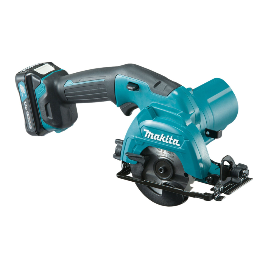
HS301D
85mm (3-3/8") Cordless Circular Saw
) platform. The new platform has
*1
Model
50, 70, 130 with DC10WC
22, 30, 60 with DC10SA
Diameter
Hole diameter
at 0°
at 45°
: kg (lbs)
4
*5 Battery / Charger / Plastic carrying case are not supplied with "Z" model.
*6 Supplied with the same quantity of extra Battery.
Note: The standard equipment may vary by country or model variation.
5
Battery BL1015 (BL1016*
Battery BL1020B (BL1021B*
Battery BL1040B (BL1041B*
Charger DC10SA (DC10SB*
Charger DC10WC (DC10WD*
HS301D
10.8
1.5, 2.0, 4.0
17, 22, 44
Li-ion
Slide
160
85 (3-3/8)
15 (9/16)
1,500
0 - 45
25.5 (1)
16.5 (5/8)
Yes
Yes
Yes (on the battery)
1.6 (3.5)*
2
1.8 (3.9)*
3
)
1
)
1
)
1
1)
1)
OFFICIAL USE
for ASC & Sales Shop
PRODUCT
December 2015
H
L
Dimensions: mm (")
313 (12-3/8)
Length (L)
331 (13)
Width (W)
170 (6-11/16)
Height (H)
155 (6-1/8)
*2 With BL1015 / BL1020B
*3 With BL1040B
P 1/ 17
W
*2
*3
Advertisement

Related Manuals for Makita HS301D


Summary of Contents for Makita HS301D
- Page 1 ASC & Sales Shop ECHNICAL INFORMATION PRODUCT P 1/ 17 December 2015 Model No. HS301D Description 85mm (3-3/8") Cordless Circular Saw ONCEPT AND MAIN APPLICATIONS We have launched a new 10.8V (12V max ) platform. The new platform has been developed based on the current one, and features newly developed slide Li-ion battery instead of stick one;...
- Page 2 Ball bearing 604ZZ BEARING PLATE 10MM 1R361 disassembling / assembling Bearing retainer 14-23 BEARING RETAINER TIGHTEN' TOOL [2] LUBRICATION Apply Makita grease FA. No.2 to the parts designated with black triangle. Symbol of Item No. Description Portion to lubricate Amount...
- Page 3 P 3 / 17 epair [3] DISASSEMBLY/ASSEMBLY [3]-1 Tightening torque for Screws Tightening Screw or Bolt Q’ty Use for torque (N.m) 12 ~ 16 fixing Ball bearing 6900DDW (32) in Bearing box (34) Bearing retainer 14-23 (31) M5x16 counter sunk 2.4 ~ 3.5 fastening Bearing retainer (34) to Handle set R (17) (36)
- Page 4 P 4 / 17 epair [3] DISASSEMBLY/ASSEMBLY [3]-2 Base ASSEMBLING Assemble the component parts to Base. Fig. 4 < Note > Assemble Depth guide (53) to the outside of Base (59). (53) (59) [3]-3 Lock off lever, Switch lever DISASSEMBLING Fig.
- Page 5 P 5 / 17 epair [3] DISASSEMBLY/ASSEMBLY [3]-4 Safety cover DISASSEMBLING Fig. 6 1. Remove Retaining ring WR-26 (41) using 1R003 with 1R212. Remove Flat washer 26 (40). (38) 2. Release Tension spring 4 (38) from Safety cover (39). 1R003 (41) 1R212 (40)
- Page 6 P 6 / 17 epair [3] DISASSEMBLY/ASSEMBLY [3]-5 Helical gear 47, Helical gear 9B, Ball bearing 606ZZ Ball bearing 604ZZ DISASSEMBLING Fig. 9 (17) 1. Unscrewing six 4x18 Tapping screws (16), separate Handle set L (7) from Handle set R (17). (16) : 6 pcs.
- Page 7 P 7 / 17 epair [3] DISASSEMBLY/ASSEMBLY [3]-5 Helical gear 47, Helical gear 9B, Ball bearing 606ZZ Ball bearing 604ZZ DISASSEMBLING Fig. 12 4. When replacing Ball bearing 604ZZ (25), hold it with a pair of 1R356 by inserting 1R278 them into the gap between Helical gear 47 (26) and Ball bearing 1R356...
- Page 8 P 8 / 17 epair [3] DISASSEMBLY/ASSEMBLY [3]-5 Helical gear 47, Helical gear 9B, Ball bearing 606ZZ Ball bearing 604ZZ ASSEMBLING Fig. 14 1. Press fit Ball bearing 606ZZ (27) to Helical gear 9B (28) with 1R027. 2. Press fit Helical gear 47 (26) 1R027 1R028 to Helical gear 9B (28) with...
- Page 9 P 9 / 17 epair [3] DISASSEMBLY/ASSEMBLY [3]-6 Helical gear 28, Ball bearing 6900DDW DISASSEMBLING 1. Remove Retaining ring WR-26 (41) using 1R003 to which 1R212 is attached. And then, remove Flat washer 26 (40). See Fig. 6. 2. Release Compression spring 4 (38) from Safety cover (39). Safety cover can be disassembled from the machine.
- Page 10 P 10 / 17 epair [3] DISASSEMBLY/ASSEMBLY [3]-6 Helical gear 28, Ball bearing 6900DDW DISASSEMBLING Fig. 20 7. Protecting Bearing box (34) with 1R041, set it as drawn. 8. Remove Bearing retainer (35) with 1R361 1R361 1R361 by turning counterclockwise. 1R041 (35) (34)
- Page 11 P 11 / 17 epair [3] DISASSEMBLY/ASSEMBLY [3]-6 Helical gear 28, Ball bearing 6900DDW ASSEMBLING Fig. 23 1. Put Ball bearing 6900DDW (32) into Bearing box (34). (31) (32) 2. Put Bearing retainer 14-23 (31) on Ball bearing 6900DDW (32). No need to tighten Bearing retainer 14-23 (31) firmly.
- Page 12 P 12 / 17 epair [3] DISASSEMBLY/ASSEMBLY [3]-6 Helical gear 28, Ball bearing 6900DDW ASSEMBLING Fig. 26 6. Do not forget to mount O ring 26 (33) to (33) Bearing box (34) at the illustrated portion. 7. Do not forget to mount Thickness ring (37) to Bearing box (34) at the illustrated portion.
- Page 13 P 13 / 17 epair [3] DISASSEMBLY/ASSEMBLY [3]-6 Helical gear 28, Ball bearing 6900DDW ASSEMBLING Fig. 28 1. Unscrewing six 4x18 Tapping screws (6), disassemble Handle set L (17). (17) Fig. 29 2. Unscrewing three 4x30 Tapping screws (2), disassemble Motor housing set (1) (3).
- Page 14 P 14 / 17 ircuit diagram Fig. D-1 Color index of lead wires' sheath Black DC Motor White Yellow Red point mark Flag receptacle with lock (#250, t=0.8mm) Line filter (if used) Controller 16 AWG* Flag receptacle without lock (#187, t=0.5mm) 16 AWG* Switch 16 AWG*...
- Page 15 P 15 / 17 iring diagram Fig. D-2 Wiring to DC Motor Red point mark Connect Flag receptacles to DC Motor (20) as follows. * Connect receptacle with red lead wire to the Motor terminal designated with red point mark. * Connect terminals so that the lead wires are guided to Motor housing L (1) side as illustrated.
- Page 16 P 16 / 17 iring diagram Fig. D-4 Wiring of Controller Unit (17) Put Controller (10) to Handle set R (17) as follows. * Facing its three lead wire side (white), (yellow), (black) to the bottom of Handle set R (17) * Facing its two lead wire side (red), (black) for connecting to DC motor, to Handle set L side...
- Page 17 P 17 / 17 iring diagram Fig. D-4 Wiring in Handle set R The lead wires bundled with tape have to be put on the lead wire (white) between Line filter and Switch (11). Put controller’s lead wires to this groove. Put Line filter to this space if it is used.
Need help?
Do you have a question about the HS301D and is the answer not in the manual?
Questions and answers