Advertisement
Available languages
Available languages
IL507001EN
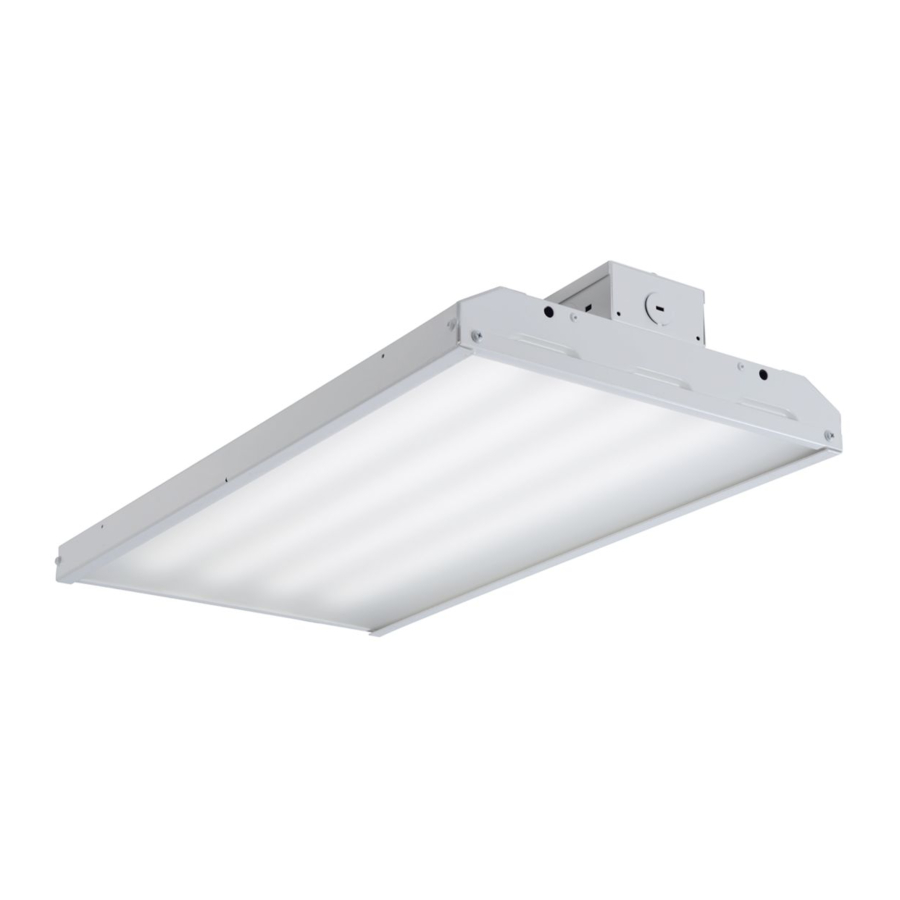
Installation Instructions – Value High Bay
Instructions d'installation – Value High Bay
Instrucciones de instalación – Value High Bay
Risk of Fire, Electrical Shock, Cuts or other Casualty Hazards- Installation and maintenance of this product
must be performed by a qualified electrician. This product must be installed in accordance with the applicable
installation code by a person familiar with the construction and operation of the product and hazards involved.
Risk of Fire and Electric Shock- Make certain power is OFF before starting installation or attempting any
maintenance. Disconnect power at fuse or circuit breaker.
Risk of Fire- Minimum 90°C supply conductors.
Risk of Burn- Disconnect power and allow fixture to cool before handling or servicing.
Risk of Personal Injury- Due to sharp edges, handle with care.
Failure to comply with these instructions may result in death, serious bodily injury and property damage.
DISCLAIMER OF LIABILITY: Cooper Lighting Solutions assumes no liability for damages or losses of any kind that may
arise from the improper, careless, or negligent installation, handling or use of this product.
IMPORTANT: Read carefully before installing fixture. Retain for future reference.
NOTICE: Green ground screw provided in proper location. Do not relocate.
NOTICE: Fixture may become damaged and/or unstable if not installed properly.
Note: Specifications and dimensions subject to change without notice.
ATTENTION Receiving Department: Note actual fixture description of any shortage or noticeable damage on delivery
receipt. File claim for common carrier (LTL) directly with carrier. Claims for concealed damage must be filed within 15 days
of delivery. All damaged material, complete with original packing must be retained.
INSTALLATION
N
Fixture to be installed no less than 18"[457mm] from the
ote:
ceiling surface.
Fixture CANNOT be used as a surface mounted fixture.
Cable/Y-Toggle Suspension Installation
1.
Locate and install cable to the support structure with the
cables spaced approximately 18"[457mm] apart.
2.
Slip the toggle ends through the holes on the upper flanges
of the end plate. (Figure 1.)
3.
Level the fixture by adjusting the cable length to the support
structure while maintaining a minimum distance to the
ceiling of 18"[457mm].
4.
Open the housing cover and locate and remove the desired
knockout for supply voltage entry.
5.
Connect input wiring to driver disconnect provided.
6.
Close cover.
WARNING
Figure 1.
Single Point Mounting Installation
Refer to Single Point Mounting Instructions, IB519029EN
included with the SPM kit sold separately.
Wire Guard Installation
Refer to Wire Guard Installation Instructions, IB519031EN
included with the Wire Guard kit sold separately.
Metalux
Advertisement
Table of Contents

Subscribe to Our Youtube Channel
Related Manuals for Cooper Metalux Value High Bay


Summary of Contents for Cooper Metalux Value High Bay
- Page 1 Failure to comply with these instructions may result in death, serious bodily injury and property damage. DISCLAIMER OF LIABILITY: Cooper Lighting Solutions assumes no liability for damages or losses of any kind that may arise from the improper, careless, or negligent installation, handling or use of this product.
- Page 2 La désobéissance aux instructions suivantes représente un risque de blessures graves ou mortelles et de dommages matériels. EXONÉRATION DE RESPONSABILITÉ : Cooper Lighting Solutions n’assume aucune responsabilité pour les dommages ou pertes de toute nature pouvant découler d’une installation inappropriée, imprudente ou négligente et d’une mauvaise manipulation ou utilisation de ce produit.
- Page 3 El incumplimiento de estas instrucciones puede ocasionar la muerte, lesiones corporales graves y daños a la propiedad. RENUNCIA DE RESPONSABILIDAD: Cooper Lighting Solutions no asume ninguna responsabilidad por daños o pérdidas de ningún tipo que puedan surgir por la instalación, manipulación o uso inadecuado, descuidado o negligente de este producto.
- Page 4 Visite www.cooperlighting.com para conocer nuestros términos y condiciones. Cooper Lighting Solutions 1121 Highway 74 South Peachtree City, GA 30269 P: 770-486-4800 Cooper Lighting Solutions is a registered www.cooperlighting.com trademark. All trademarks are property of their respective owners. Product availability, specifications,...
Need help?
Do you have a question about the Metalux Value High Bay and is the answer not in the manual?
Questions and answers