Advertisement
Quick Links
IB505061EN
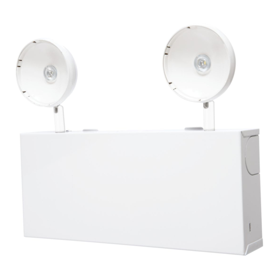
Installation Instructions for the Sure-Lites SELM25R16SD/ SELM50R14SD/
SELM60R10SD Emergency Light
WARNING
Risk of Fire/Electric Shock
If not qualified, consult an electrician.
IMPORTANT SAFEGUARDS
WHEN USING ELECTRICAL EQUIPMENT, BASIC SAFETY
PRECAUTIONS SHOULD ALWAYS BE OBSERVED INCLUDING
THE FOLLOWING.
READ AND FOLLOW ALL
SAFETY INSTRUCTIONS
1. Do not use outdoors.
2. Do not use in hazardous locations, or near gas or electric
heaters.
3. Do not let power supply cords touch hot surfaces.
4. Do not use this equipment for other than the intended use.
5. Installation is to be performed only by qualified personnel.
6. Install in accordance with National Electric Code and local
regulatory agency requirements.
7. The use of accessory equipment not recommended by the
manufacturer may cause an unsafe condition.
8. Equipment should be mounted in locations and at heights
where it will not readily be subjected to tampering by
unauthorized personnel.
SAVE THESE
INSTRUCTIONS
MAX MOUNTING HEIGHT: 27.6 ft.
INSTALLATION
1. De-energize the circuit at the junction box (J-box) where
the emergency light is to be installed.
2. Open the emergency light by removing the sheet metal
screw from the bottom of the fixture, then tipping the
cover up off of the backplate (See Fig. 1).
3. To mount to a junction box - Knock out the appropriate
mounting pattern and the wire pass hole in the backplate
to fit the J-box being used.
049-292
Risk of Electric Shock
Disconnect power at fuse or circuit breaker before
installing or servicing.
4. To mount using conduit, mount the backplate to the wall
NOTE: A fourth conduit mount location is available on the
5. Once the backplate is secured, the housing can be held in
6. Connect incoming ground to the green ground wire.
7. Connect the incoming wires to the fixture's power supply
8. Determine the incoming voltage, and select the appropriate
9. LED remotes can be connected using the violet (+) and yellow
10. Replace the housing onto the backplate. Secure the
11. Remove EZ Key to connect the battery. Battery will not
12.Energize AC supply. The test button should illuminate, and
13.Adjust remote heads (not included) as needed.
14.Allow 24 hours for batteries to charge.
15.If the fixture is to be powered down for an extended period
SURE-LITES
WARNING
in the desired location. Attach a conduit hub to whichever
of the three conduit mount points on the backplate is most
convenient. (see Fig. 2) Remove the corresponding U shaped
cover from the housing by wiggling it back and forth until it
breaks free. (see Fig. 3)
bottom surface of the housing, but it can only be used with
flex conduit.
place during installation using the EZ Hang feature. (Fig. 2)
wires using the wire nuts provided. Connect the white
wire to neutral. Connect the black wire to the hot lead.
The SELM25R16SD / SELM50R14SD / SELM60R10SD uses
a universal input power supply that will accept from 120-
277VAC (see Schematic).
jumper for the brownout circuit (see Schematic). Because of
the universal input of the SELM25R16SD / SELM50R14SD /
SELM60R10SD, the battery charger will continue to function
if voltage sags, even if the normal power lights in the area
fail. Selecting the appropriate incoming voltage sets the
voltage threshold for the brownout circuit, so that the
emergency lights will come on if voltage sags. The fixture
ships with the circuit set to 120V.
(-) wires. See schematic.
backplate with the sheet metal screw.
charge with the EZ Key in place.
the LED heads will illuminate briefly when the test button is
pushed.
after initial installation, replace the EZ Key. This will prevent
the battery from discharging when AC power is removed.
However, it will also prevent the battery from charging when
AC power is restored, so it must be removed once the unit is
ready for regular operation.
INS #
Advertisement

Related Manuals for Cooper SURE-LITES SELM25R16SD


Summary of Contents for Cooper SURE-LITES SELM25R16SD
- Page 1 SURE-LITES INS # IB505061EN 049-292 Installation Instructions for the Sure-Lites SELM25R16SD/ SELM50R14SD/ SELM60R10SD Emergency Light WARNING WARNING Risk of Fire/Electric Shock Risk of Electric Shock If not qualified, consult an electrician. Disconnect power at fuse or circuit breaker before installing or servicing.
- Page 2 Installation Instructions for the Sure-Lites SELM25R16SD /SELM50R14SD /SELM60R10SD Emergency Light Figure 1 SETTING BROWN OUT CIRCUIT Because of the universal input of the SELM25R16SD / SELM50R14SD / SELM60R10SD, the battery charger will continue to function if voltage sags, even if the normal power lights in the area fail.
- Page 3 Installation Instructions for the Sure-Lites SELM25R16SD /SELM50R14SD/SELM60R10SD Emergency Light MAINTENANCE Clearing Failure Code • A battery failure (LED two blink red) can be cleared by replac- None required. Replace the batteries as needed according to ing the battery. Disconnecting the battery and AC power, or ambient conditions.
Need help?
Do you have a question about the SURE-LITES SELM25R16SD and is the answer not in the manual?
Questions and answers