Table of Contents
Advertisement
Quick Links
Service Manual
Baby scale
KERN MBC-(E)
Typ MBC 15K2DNM (DEM)
Typ MBC 20K10NM (EM)
Version 1.1
02/2020
GB
KERN & Sohn GmbH
Ziegelei 1
D-72336 Balingen
E-Mail: info@kern-
sohn.com
Tel: +49-[0]7433- 9933-0
Fax: +49-[0]7433-9933-
149
Internet: www.kern-
sohn.com
Importør:
Impex Produkter AS
Gamle Drammensvei 107
1363 Høvik
www.impex.no
info@impex.no
Tel.: 22 32 77 20
MBC-NM-SH-e-2011
Advertisement
Table of Contents

Related Manuals for KERN MBC-(E)


Summary of Contents for KERN MBC-(E)
- Page 1 KERN & Sohn GmbH Ziegelei 1 Tel: +49-[0]7433- 9933-0 Fax: +49-[0]7433-9933- D-72336 Balingen E-Mail: info@kern- Internet: www.kern- sohn.com sohn.com Service Manual Baby scale Importør: Impex Produkter AS Gamle Drammensvei 107 1363 Høvik www.impex.no KERN MBC-(E) info@impex.no Tel.: 22 32 77 20...
-
Page 2: Table Of Contents
KERN MBC Version 1.1 02/2020 Servicemanual Contents Basic Information................... 3 Introdution ...................... 3 Appliance overview ..................4 Overview of display ........................5 Keyboard overview ........................6 Levelling ......................7 Rechargeable battery operation (MBC-A08) ................7 Battery operation ........................8 Insert batteries ..........................8 Mains connection ........................ -
Page 3: Basic Information
1 Basic Information The device must be repaired only by trained specialist staff or personnel with professional formation (such as a repair-specialist accredited by law concerning verification). The service manual is obligatory for repair work. After repair, original conditions of the device have to be restored. -
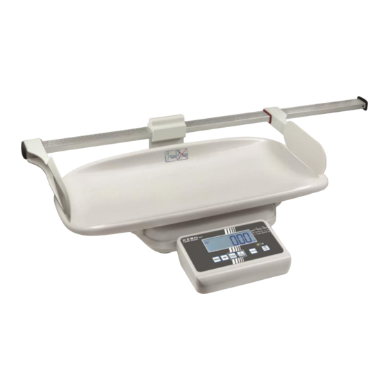
Page 4: Appliance Overview
3 Appliance overview 1. Height measuring rod (optional) 2. Bubble level 3. Display Unit 4. LED 5. Baby weighing pan 6. Weighing pan 7. Rubber feet (height adjustable) 8. Mains connection 9. Battery compartment 10. RS232 MBC-NM-SH-e-2011... -
Page 5: Overview Of Display
3.1 Overview of display Display Description Description GROSS Gross weight display Lights up during indication of the gross weight of the baby (after drinking) Net weight display Lights up during indication of the net weight of the baby (before drinking) Illuminated after weighing scale was tared ZERO Zeroing display... -
Page 6: Keyboard Overview
3.2 Keyboard overview Typ MBC 15K2DNM Typ MBC 20K10NM Description Function ON/OFF-switch Turn on/off Weighing scale will be reset to „0.0“ kg. Zeroing key For numeric entry: Change decimal place HOLD button Hold function TARE button Tare balance Feeding Function Differential weighing before and after the baby drinks The net weight of the baby will be shown: Before drinking... -
Page 7: Levelling
4 Levelling Level balance with foot screws until the air bubble of the water balance is in the prescribed circle. 4.1 Rechargeable battery operation (MBC-A08) (is possible by obtaining an optional battery power pack) Open the battery compartment cover (1) at the base of the display unit and insert the rechargeable battery pack. -
Page 8: Battery Operation
4.2 Battery operation As an alternative to rechargeable battery operation, the balance may also be operated with 6x AA batteries. Open battery compartment cover (1) at the lower side of the display unit and insert batteries according to the example below. Lock the battery cover again. If the batteries are empty, in the balance display appears the symbol . -
Page 9: Mains Connection
Power is supplied by the external power unit which also serves to isolate the mains supply from the scale. The stated voltage value must be the same as the local voltage. Only approved genuine KERN power supply units may be used in compliance with Directive EN 60601-1. -
Page 10: Menu
5 Menu Access to service menu „tCH“is locked in verified balances. To disable the access lock, destroy the seal and actuate the adjustment switch. For position of adjustment switch, see Instruction manual MBC chap. 13. Attention: After destruction of the seal the weighing system must be re-verified by an authorised agency and a new verification wire/seal mark fitted before it can be reused for applications subject to verification. -
Page 11: Menu Overview
5.2 Menu overview Function Settings Description F1 oFF oFF 0* Automatic shutdown off Automatic cutout oFF 3 Automatic shutdown after 3 min Auto Off oFF 5 Automatic shutdown after 5 min oFF 15 Automatic shutdown after 15 min oFF 30 Automatic shutdown after 30 min F2 bk bl on... - Page 12 P2 CAL duA in dESC C 0.00 C 0.000 C 0.0000 C 0.0 Sd iv 1 div 1, 2, 5, 10, 20, 50 Sd iv 2 div 1, 2, 5, 10, 20, 50 CAP 1 CAP 2 UnLoAd StrAnG St 100 St 200 St 500 duA rA...
-
Page 13: Position Adjustment Switch And Seals
P3 Pro Not documented CoUnt Not documented rESEt Reset weighing scale to factory setting SEtGrA Not documented * default setting 6 Position adjustment switch and seals: Self-destroying seal mark Cover Adjustment switch MBC-NM-SH-e-2011... -
Page 14: Adjustment
1. Carry out adjustment as closely as possible to admissible maximum load of weighing scale. Information about test weights you will find in the internet under http://www.kern-sohn.com Observe stable environmental conditions. For warm-up time required for stabilisation see Instruction manual MBC chpt 1. -
Page 15: Procedure
7.1 Procedure: Turn on the scale during the self-test press , the first function [F1 oFF] is displayed. Press repeatedly until "t CH" is displayed. Press , [Pin] is displayed Operate adjustment switch; for position see chap.13 Press subsequently, [P1 SPd] will appear ... - Page 16 Ensure that there are no objects on the weighing pan. Wait for stability display "STABLE", then confirm with The size of the currently set adjustment weight is displayed, the active site flashes. (example) If required, select with he digit to be altered and change the digit with Confirm with...
-
Page 17: Maintenance
8 MAINTENANCE 8.1 General Please clean the scale each week and do calibration every year. If the scale does not operate properly, find out the problem as possible. Determine whether the problem is constant or alternate. Be aware that problems can be caused by mechanical or electrical influences. -
Page 18: Load Cell Connections
8.5 Load Cell Connections Signal Green Supply + Signal Black Supply - White Shield Measuring Points Resistance Red (+ Exc) to White ( –Exc) 420 ±20Ω Green (+Sig) to Black ( –Sig) 350Ω ±5Ω 8.6 Checking the different Voltages If the problem is in the PCB, use a multimeter to check the following voltages AC Power Check the AC power socket out put voltage. -
Page 19: Trouble Shooting
8.7 Trouble Shooting Problems Possible cause Common Solutions Display is blank. Mains power is turned Check power is getting inside the scale No self test off. Power supply faulty and on/off switch is working. or not plugged. Internal Verify the voltages, which is on the battery is not charged. -
Page 20: Drawing
DRAWING MBC HM MBC-NM-SH-e-2011... -
Page 21: Mbc Ohm
MBC oHM MBC-NM-SH-e-2011...
Need help?
Do you have a question about the MBC-(E) and is the answer not in the manual?
Questions and answers