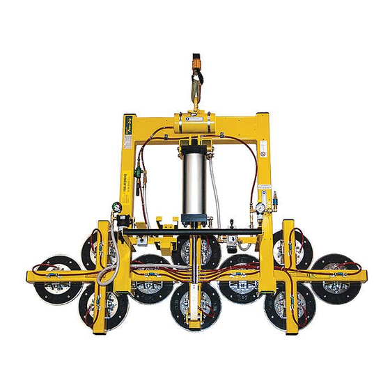
Summary of Contents for WOOD'S POWR-GRIP POWER TILT
- Page 1 LEAK TEST PROCEDURE POWER TILT [PT] MODEL LIFTERS WITH AIR POWER SYSTEMS TESTING AND MAINTENANCE MUST BE DONE BY A QUALIFIED PERSON KEEP FOR FUTURE REFERENCE TST-020 PT-AIR – REV. 2017-246...
- Page 2 TST-020 PT-AIR – REV. 2017-246...
-
Page 3: Table Of Contents
TABLE OF CONTENTS LEAK DETECTION SYMPTOMS OF VACUUM LEAK DETERMINING LEAK EXISTENCE ADDRESSING LEAK BASIC REPAIR TIPS PRELIMINARY TEST VACUUM GENERATING SYSTEM TEST PAD SYSTEM TESTS SYSTEM CONFIRMATION DIAGNOSTICS AIR POWERED PUMP [VENTURI] DIAGNOSIS ACTUATOR TILTS AFTER STOPPING ADDITIONAL INFORMATION TST-020 PT-AIR –... -
Page 4: Symptoms Of Vacuum Leak
SYMPTOMS OF VACUUM LEAK A severe leak is evidenced by a lifter’s inability to draw full vacuum while attached to a clean, smooth, nonporous surface. In such cases, the vacuum level shown on the vacuum gauges will be less than 16" Hg [-54 kPa], the red zone of the vacuum gauge. A moderate leak is indicated if the lifter loses more than 4"... -
Page 5: Basic Repair Tips
BASIC REPAIR TIPS 1) When removing a hose from a barbed fitting, avoid damaging the barbs of the fitting to which the hose is attached. Cuts or nicks in fitting barbs can create a leak that did not previously exist. 2) If a hose is removed from a barbed fitting, cut approximately 1/8"... -
Page 6: Preliminary Test
PRELIMINARY TEST Note: The following assumes operator has access to suitable plugs to seal off the section being tested. This test determines whether leakage is located in the vacuum generating system or the pad system. 1) Remove the hose from the vacuum filter that attaches to the vacuum pad system. -
Page 7: Vacuum Generating System Test
VACUUM GENERATING SYSTEM TEST Note: The following assumes operator has access to suitable plugs, a ball valve with vacuum gauge, and additional hose and adapter fittings for connecting the ball valve to the lifter’s vacuum lines and fittings. The most likely leak points in the vacuum generating system are the check valve, the filter, or the control valve. - Page 8 If the vacuum level of both the lifter and ball valve’s vacuum gauges start and continue to drop: The check valve leaks and needs to be replaced and there is a leak located in either the filter or control valve assembly. First, replace the check valve then proceed to step 5.
- Page 9 9) To individually test the filter, leave the ball valve connected to the venturi pump. Connect the end of the ball valve connected to the control valve directly to the hose of the vacuum filter assembly. Cap off the fitting of the filter that was connected to the vacuum pads if it is not capped-off.
- Page 10 Once the vacuum generating system is confirmed to hold (no significant leaks noted per the vacuum readings), re-connect the pad system, proceed to system confirmation and retest the vacuum system as described. TST-020 PT-AIR – REV. 2017-246 Page 7 of 14...
-
Page 11: Pad System Tests
PAD SYSTEM TESTS Note: The following assumes operator has access to suitable plugs, a ball valve with vacuum gauge, and additional hose and adapter fittings for connecting the ball valve to the lifter’s vacuum lines and fittings. If it was determined that the vacuum generating system does not leak, or if any existing leaks in the vacuum generating system have been repaired, proceed with the following: Isolate the vacuum pads, fittings and vacuum line sections until the leak point can be located: Lifter models with shut-off valves on all vacuum pads:... - Page 12 5) Observe the vacuum gauge. If the vacuum level of the lifter’s vacuum gauge holds steady and does not drop: The leak is located in one or more of the vacuum pads. Re-attach one pad at a time to determine which vacuum pads are leaking. Repair or replace as needed.
-
Page 13: System Confirmation
SYSTEM CONFIRMATION Once all leaks have been identified and repaired, reassemble all parts of the lifter. A vacuum test, as described in the instruction manual, should be performed following any repair or service to a vacuum lifter. Note: If system is equipped with shut-offs or quick connects, a vacuum test should be performed with these parts in every manner of use (i.e. -
Page 14: Diagnostics
DIAGNOSTICS VENTURI AIR POWERED PUMP DIAGNOSIS: A problem with the venturi air pump is indicated when the lifter cannot attain sufficient vacuum (>16" Hg [54 kPa]) but does not leak when a vacuum test is performed. Requirements: The power requirements of the venturi is designated by a pressure rating (in psi or kPa) and a flow rating (in SCFM or liters/minute). -
Page 15: Actuator Tilts After Stopping
Perform a vacuum test. If the vacuum level still does not reach a sufficient level (>16" Hg. [54 kPa]) remove the muffler (unscrew counter-clockwise) from the venturi assembly to determine if a restriction exists. (See FIGURE 12 Repeat the vacuum test. If the lifter does pull sufficient vacuum (>... - Page 16 The tilt control valve consists of an incoming airline ( two vent plugs ( ) and two feed lines ( When the handle is in the center position, all the ports are closed. A leak is indicated when the handle is in the center and air is flowing from the vent ports or from the ports to the feed lines of the actuator.
-
Page 17: Additional Information
ADDITIONAL INFORMATION 1) When requesting information on a particular lifter, please have the model number and serial number available. 2) CAUTION: Always proceed with caution when opening enclosures containing electrical wiring. Wiring is often connected to components in the cover, as well as the enclosure itself.


Need help?
Do you have a question about the POWER TILT and is the answer not in the manual?
Questions and answers