Advertisement
Table of Contents
- 1 Table of Contents
- 2 Safety Precautions
- 3 Cautions on Safe Use of this Product
- 4 Confirmation at Unpacking
- 5 Names and Functions
- 6 Description of Operation Panel
- 7 Preparations
- 8 Method of Change to Japanese Display
- 9 Method for Changing the Setting Mode
- 10 Setting of Interface
- 11 Connection of Barcode Scanner
- 12 Troubleshooting
- 13 Daily Maintenance
- 14 Cautions on Use of Printer Driver
- Download this manual
Advertisement
Table of Contents

Summary of Contents for ESPO PATH SLIDE PRINTER
- Page 1 Format number: 066-52+77A01 Document number 418-00-11-01-09 Revision number Date of establishment March 23, 2017 Date of revision January 9, 2018 ESPO PATH SLIDE PRINTER Instruction Manual...
- Page 2 FCC compliance Statement FCC WARNING: Ch a ng e or m od if ic at i o ns n ot ex pr es s l y ap pr o v ed b y th e par t y r es p o ns ib l e f or c om p l ia nc e c ou l d v o id t h e us e r ’s a ut h or it y t o o per at e t he eq u i p m ent.
-
Page 3: Table Of Contents
Contents Safety precautions ........4 Cautions on safe use of this product ..5 Confirmation at unpacking ......8 Names and functions ....... 12 Description of operation panel ....14 Preparations ..........17 Method of change to Japanese display . 23 Method for changing the setting mode .. -
Page 4: Safety Precautions
Safety precautions Meaning of icons This section describes various cautions for using the product safely using icons. Each meaning is shown below. Describes the content that may cause death or heavy injury of user WARNING if the product is handled wrongly ignoring this indication. Describes the content that may cause physical loss such as disability of user if the product is handled wrongly ignoring this CAUTION... -
Page 5: Cautions On Safe Use Of This Product
Cautions on safe use of this product * Be sure to follow the content shown below to use this product safely. Do not carry out any item that is not shown in this section. WARNING Do not install the device at an unstable place or place where there is vibration. - Page 6 When you pull out the power cord, be sure to hold the plug. If you pull the cord, the power cord may be damaged and fire or electric shock may be caused. Do not use this product at the power supply voltage other than AC100 –...
- Page 7 CAUTION Do not install the device at a place where there is much humidity or dust, place where is exposed to direct sunlight, highly humid place, or place near fire. Otherwise, fire or electric shock may be caused. Ambient temperature is 5 to 35 C, humidity is 35 to 80% (no dew condensation) Use the product within the specification range shown above.
-
Page 8: Confirmation At Unpacking
Confirmation at unpacking * Open the package and check if there are following accessories. <CAUTION> The packing box and the interior material are required for transportation. Be sure to keep them. Main unit AC adapter Power cable Magazine (option) Ribbon cassette Front cover cap Spool holder Set on the main unit... - Page 9 Simplified installation manual Driver CD Fall-prevention stay (with screw) Antenna for wireless LAN Japanese CAUTION stickers Removal of fixing bracket for transportation Head unit and magazine holder are fixed with fixing bracket as a measure against failure at transportation. Remove them before using the product. Head unit fixing bracket Magazine holder fixing bracket Unscrew two screws at each point.
- Page 10 How to attach the fixing bracket Keep the removed screws and brackets not to lose. They are required for transportation. Attachment of fall-prevention stay Attach the fall-prevention stay preventing this product from falling during the use. Unscrew two binding screws (M3) that have been secured. Fix the stay with two countersunk screws (M3) included with the product.
- Page 11 Replacement of CAUTION sticker If the place where the product is used is Japan, please change the attached CAUTION sticker to Japanese version. Change of language display on touch panel liquid crystal display When the product is shipped, the language display is set to English. To change it to Japanese, change the language display to Japanese referencing “...
-
Page 12: Names And Functions
Names and functions (3) (4) (10) (6) (7) Name Function Power switch Power switch of main unit Liquid crystal display / Status display and change of setting can be operation section implemented from touch panel liquid crystal display Removable tray for collecting the dust removed from Dust tray frost surface Cover to be opened when accessing the inside of... - Page 13 When the open cover is opened (11) (12) (13) (14) (15) (16) Name Function (11) Ribbon cassette Cassette in which ink ribbon is set (12) Head unit Transcribes the ink ribbon to the frost section by heat (13) Dust tray Tray for collecting the removed glass powder (14) Tweezers holder...
-
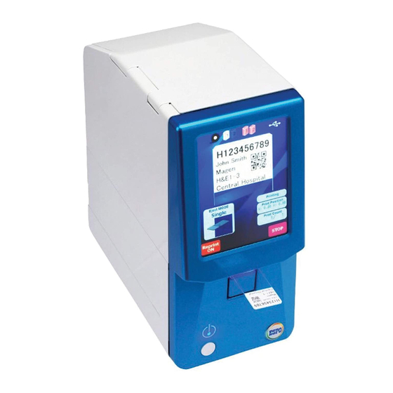
Page 14: Description Of Operation Panel
Description of operation panel Copy mode standby screen (This is the display when the language is set to ENGLISH) Item Function Display Description Ribbon level display Displays the residual quantity of ink ribbon. The residual quantity is displayed in three levels. Magazine set display Displays whether a magazine is set or not. - Page 15 Preview display Displays the print data to be printed. Switching of Displays the setting mode of Single mode Continuous mode discharge mode discharge operation. * When the front loading is used, the frost direction varies between front 1 and front 2. Front 1 mode Front2 mode Print position...
- Page 16 Reprint mode screen Switching of Switches to usual reprint mode mode Selection of Switches the magazine magazine Print Executes reprint Print position correction mode screen Position Press the arrows to correction correct the print position. The print position is registered by pressing OK.
-
Page 17: Preparations
Preparations [1] Open the upper cover. [2] Pull out the ribbon cassette. Hold the handle and pull it out in a transverse direction. Ribbon cassette [3] Pull out the spool holder from the ribbon cassette. Pull it out straightly along the groove. Spool holder... - Page 18 [4] Set an ink ribbon in the spool holder. The ink surface is outside. Set the ink ribbon in the spool holder so that the ink surface faces outside. [5] Set the ink ribbon in the ribbon cassette. Spool catch Insert the spool holder in the spool catch surely.
- Page 19 Wind-up side Let-off side [6] Set the ribbon cassette in the main unit. [7] Set a slide glass in the metallic magazine. (1) Press the button * The disposable magazine can be set directly. (2) Raise the cover...
- Page 20 Set a slide glass in the magazine. Frost surface Frost side For the slide glass at the bottom, the frost surface is reversely set. When you set it in the magazine, change the direction. Two magazines can be set. The magazine on the right side seen from the front surface of device is magazine 1 and the left side is the magazine 2.
- Page 21 [8] Set the power supply (DC jack). DC input part Lace it in the retainer clip [9] Set the interface cable. Lace it in the retainer clip Wireless LAN Wireless LAN antenna [10] Select and attach cap, stacker, and tray. Front cover cap Select a part to be attached to...
- Page 22 In the single sheet mode, set the front cover cap (attached when the product is shipped). How to remove the front cover cap To use the product in the continuous mode, set the 20-sheet stacker. To use the product for front loading, set the manual feeding tray.
-
Page 23: Method Of Change To Japanese Display
Method of change to Japanese display Here shows the method for changing the language display to Japanese. The mode shifts to setting mode. 3. Select “Other setting”. 2. Change language from ENGLISH to JAPANESE and press button to return to the setting main screen. JAPANESE Press “Update”... -
Page 24: Method For Changing The Setting Mode
Method for changing the setting mode Here shows the method for changing the setting of printer. mode shifts setting mode. The following settings are available. 1. Interface setting 2. Machine setting 3. Other setting 1.Interface setting Change of operation mode 1.Interface select Set the interface when the product is used by connecting it to PC. - Page 25 3. Eject Mode select Set the default (when the power supply is turned ON) discharge mode. Continuous Printing is executed continuously. Single Each sheet stops at the discharge section. Front loading 1 Manual feeding mode 1 Front loading 2 Manual feeding mode 2 The direction of frost varies between 1 and 2.
- Page 26 Change of wireless LAN mode 1. Used area 2. DHCP 3. IP address 4. Subnet mask 5. Default gateway router setting Carry out each setting. 6. Show MAC address. 2. Machine setting Various settings of printer can be implemented. 1.Print density The print density can be corrected.
- Page 27 3. Other setting It is possible to set or implement power saving standby switching time, language display switching, firmware update. 1.Power saving wait time Set the power saving standby time. 2. LCD language Switch the language to be displayed on LCD (English, Japanese).
-
Page 28: Setting Of Interface
Setting of interface [1] USB ID The initial value of USB ID is set to “1”. [2] Port No. of network Command (bidirectional Command (simplex Interface Printer driver mode) mode) Protocol RAW Port TCP 51000 Port TCP 51000 Port TCP9100 Protocol RAW Wireless LAN Port TCP 51000... -
Page 29: Connection Of Barcode Scanner
Connection of barcode scanner To use the product by connecting a barcode scanner to ESPO, it is necessary to carry out the setting as shown below. Setting of prefix and suffix Prefix: STX (Ctrl + B), Suffix: ETX (Ctrl + C) -
Page 30: Troubleshooting
Troubleshooting [1] Description of error or alarm and coping process Indication Description Coping process Ribbon end The ribbon runs short. Change the ribbon. The magazine runs short of slide Replace the magazine to the magazine Glass empty glass. in which slide glasses are set. Head break The thermal head is damaged. - Page 31 The transfer unit can be pulled out forward. The transfer unit can be pulled out by disconnecting the connector. Remove the glass and restore the unit the way it was. Be sure to restore the connector too. If a glass is clogged in the lower part of magazine, the glass can be pulled out by removing the magazine.
- Page 32 The magazine 2 can be pulled out backward in a same way.
-
Page 33: Daily Maintenance
Daily maintenance This printer requires daily maintenance to use it safely. [Caution on cleaning] Before cleaning, be sure to turn OFF the power supply of the printer. At the cleaning, wipe off each part using a soft cloth such as waste cloth impregnated with dehydrated ethanol. - Page 34 Cleaning of platen roller (indication of cleaning: after the operation is terminated) Open upper cover and front cover. Disconnect the connector and pull out the transfer unit. While the lock nail is pushed toward (1), pull out the connector downward (2). Remove the taint attached to the platen roller using an air blow etc.
- Page 35 Cleaning of synchronized roller (indication of cleaning: at the replacement of ribbon) Open upper cover and front cover. Remove the ribbon cassette, and then remove the ink ribbon from the cassette. Clean up the platen roller using a waste cloth impregnated with dehydrated ethanol.
-
Page 36: Cautions On Use Of Printer Driver
Cautions on use of printer driver 1.This driver is GDI printer driver. In case of output from WPF application or output of XPS file, the print quality may get deteriorated. 2. If barcode / 2D code image created on the application software is magnified at the printing, deterioration such as strain and thickening / thinning of image will be generated to cause reading failure. - Page 37 Title Revision history Revision history Date of Rev. Review / Page establishment Content of revision Creation approval / revision March 23, 2017 Newly established pages June 1, 2017 Full review pages P. 27 Setting of interface is added P. 28 Setting at barcode connection and restriction of digit July 6, 2017 number are added...
- Page 38 ESPO PATH SLIDE PRINTER Instruction Manual...
Need help?
Do you have a question about the PATH SLIDE PRINTER and is the answer not in the manual?
Questions and answers
How to delete a slide information on screen? example: on my screen is John Doe and Ralph Jones is the correct one. John Doe is stuck on the screen. Is the only way to back out is to shut off the printer each time?