Table of Contents

Related Manuals for General Pump HF18


Summary of Contents for General Pump HF18
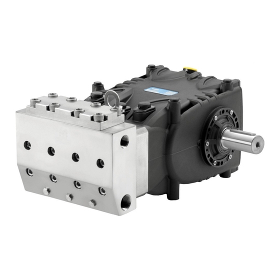
- Page 1 HF/N Serial #10127003 and Later Repair Manual HF18 - HF20 - HF22 - HF25 WK355 HF25N NOTE: This Manual covers HF pumps with Serial Numbers starting at 10127003 General Pump Ref 300623 Rev. B is a member of 10-20 the Interpump Group...
-
Page 2: Table Of Contents
HF SERIES GENERAL PUMP A member of the Interpump Group Serial #10127003 and Later INDEX INTRODUCTION ..........Page 3 REPAIR INSTRUCTIONS . -
Page 3: Introduction
Correct use and adequate maintenance is fundamental for the pump’s regular operation and long wear. General Pump declines any responsibility for damage caused by the misuse or the non-observance of the instructions described in this manual. -
Page 4: Crank Mechanism Disassembly
HF SERIES GENERAL PUMP A member of the Interpump Group Serial #10127003 and Later 2.1.1 Crank Mechanism Disassembly Dismantling the mechanical part The operations described must be performed after removing the hydraulic part, ceramic pistons and splash guards from the pump (par. 2.2.3, 2.2.4). - Page 5 HF SERIES GENERAL PUMP A member of the Interpump Group Serial #10127003 and Later Fig. 4a Fig. 4 • Remove the pump shaft • rear cover • Complete disassembly of the con-rod units by removing them from the pump crankcase and removing the plunger guide pins.
-
Page 6: Crank Mechanism Assembly
HF SERIES GENERAL PUMP A member of the Interpump Group Serial #10127003 and Later When disassembling the con-rod groups check the wear status of the piston guide rods (pos. 1, Fig. 5/d), if necessary replace them removing the 2 fixing M6 screws (pos. 2, Fig. 5/d). - Page 7 HF SERIES GENERAL PUMP A member of the Interpump Group Serial #10127003 and Later Fig. 6b • Insert the plunger/con-rod guide units into the pump crankcase, directing the numbering on the con-rod shank towards the top of the crankcase. To facilitate pump shaft insertion (without the tab), it is essential to repeat the operation performed during dis- assembly, pushing the piston/con-rod guide units as far down as possible (par.
- Page 8 HF SERIES GENERAL PUMP A member of the Interpump Group Serial #10127003 and Later • Couple the con-rod caps to their shanks, referring to the numbering (Fig. 9, pos. 1). Note the correct assembly direction of the caps. Fig. 9 •...
- Page 9 HF SERIES GENERAL PUMP A member of the Interpump Group Serial #10127003 and Later • Insert the new plunger guide seal rings as far as possible into the relative seat on the pump casing (Fig. 11), following the procedure described: use the tool code 27904900 composed of a tapered bush and a buffer.
-
Page 10: Disassembly / Assembly Of Bearings And Shims
HF SERIES GENERAL PUMP A member of the Interpump Group Serial #10127003 and Later 2.1.3 Disassembly / Assembly of Bearings and Shims The type of bearings used (tapered roller bearings), ensures the absence of axial play on the crankshaft; the shims are to be determined to reach this purpose. - Page 11 HF SERIES GENERAL PUMP A member of the Interpump Group Serial #10127003 and Later The new roller bearing can be mounted at room temperature with a press or fly press; it is necessary to lay them on the lateral side of the relevant ring nuts with opposite rings. The driving operation can be facilitated...
-
Page 12: Fluid End Repair
HF SERIES GENERAL PUMP A member of the Interpump Group Serial #10127003 and Later 2.2 Fluid End Repair 2.2.1 Disassembly of the Head - Valve Units Service operations are limited to valve inspection or replacement if needed, and in any case within the intervals indicated in the table in Chapter 11 of the Owner’s Manual. - Page 13 If the suction valve seats remain stuck on the head (for example because of incrustations due to prolonged lack of use of the pump), proceed as follows: - For HF18 versions use tools code 26019400, code 27513700, code 27513400, (Fig. 22, Fig. 22/a).
-
Page 14: Head Assembly - Valve Units
HF SERIES GENERAL PUMP A member of the Interpump Group Serial #10127003 and Later 2.2.2 Head Assembly - Valve Units Pay careful attention to the state of wear of the various components; replace them when necessary, and in any case within the intervals indicated in the table in Chapter 11 of the Owner’s Manual. - Page 15 HF SERIES GENERAL PUMP A member of the Interpump Group Serial #10127003 and Later 2. Furthermore, for the HF18A version be careful not to invert the spherical inlet valve with the “A” outlet valve (fig. 26 and fig. 27), exploded view position #46, as indicated in Chapter 16 of the Owner’s Manual.
-
Page 16: Disassembly Of The Head - Seals
HF SERIES GENERAL PUMP A member of the Interpump Group Serial #10127003 and Later 2.2.3 Disassembly of the Head - Seals The replacement of the seals is necessary if water leaks are detected from the draining holes located at the rear of the crankcase, and in any case within the intervals indicated in the table in Chapter 11 of the Owner’s... -
Page 17: Plunger Unit Disassembly
HF SERIES GENERAL PUMP A member of the Interpump Group Serial #10127003 and Later Pay careful attention to the order of sealing pack disassembly as shown in fig. 31 for HF20A/22A/25A version pumps, and fig. 31a for HF18A version composed of: 1. -
Page 18: Head Assembly - Seals - Plunger Unit
HF SERIES GENERAL PUMP A member of the Interpump Group Serial #10127003 and Later 2.2.5 Head Assembly - Seals - Plunger unit Reassemble the various components by inverting the operations previously listed in paragraph 2.2.3, paying careful attention to the following: A) Sealing packing: follow the same order used during disassembly. -
Page 19: Screw Calibration
HF SERIES GENERAL PUMP A member of the Interpump Group Serial #10127003 and Later 3. SCREW CALIBRATION Screw calibration by means of a torque wrench only. Exploded View Position Fastening Torque Fastening Torque Description (From Owner’s Manual) (Ft. Lbs.) (Nm) -
Page 20: Repair Tools
27503900 COPYRIGHT The copyright of these operating instructions is property of General Pump/ the Interpump Group. The instructions contain technical descriptions and illustrations that may not be electronically copied or reproduced, entirely or in part, nor distributed to third parties in any form without authorized written permission. -
Page 21: Maintenance Log
HF SERIES GENERAL PUMP A member of the Interpump Group Serial #10127003 and Later MAINTENANCE LOG HOURS & DATE OIL CHANGE GREASE PACKING REPLACEMENT PLUNGER REPLACEMENT VALVE REPLACEMENT GP Companies, Inc. 1174 Northland Drive Mendota Heights, MN 55120 Ref 300623 Rev. B Phone:651.686.2199 Fax: 800.535.1745...
Need help?
Do you have a question about the HF18 and is the answer not in the manual?
Questions and answers