UWT NivoGuide 8100 Instruction Manual
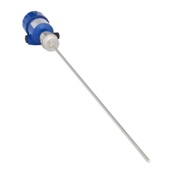
Tdr sensor for continuous level and interface measurement of liquids
Hide thumbs
Also See for NivoGuide 8100:
- Quick setup manual (17 pages) ,
- Quick setup manual (17 pages)

Related Manuals for UWT NivoGuide 8100


Summary of Contents for UWT NivoGuide 8100
- Page 1 NivoGuide® 8100 Two-wire 4 … 20 mA/HART Rod and cable probe TDR sensor for continuous level and interface measurement of liquids Technical information / Instruction manual Document ID: 58878...
-
Page 2: Table Of Contents
NivoGuide® 8100 • Two-wire 4 … 20 mA/HART Contents Contents About this document ....................... 4 Function ........................... 4 Target group ........................4 Symbols used........................4 For your safety ......................... 5 Authorised personnel ....................... 5 Appropriate use ........................ 5 Warning about incorrect use ..................... 5 General safety instructions .................... - Page 3 NivoGuide® 8100 • Two-wire 4 … 20 mA/HART Contents Trademark ........................70 Safety instructions for Ex areas Take note of the Ex specific safety instructions for Ex applications. These instructions are attached as documents to each instrument with Ex approval and are part of the operating instructions. Editing status: 2019-02-05...
-
Page 4: About This Document
NivoGuide® 8100 • Two-wire 4 … 20 mA/HART 1 About this document About this document Function This operating instructions provides all the information you need for mounting, connection and setup as well as important instructions for maintenance, fault rectification, the exchange of parts and the safety of the user. Please read this information before putting the instrument into operation and keep this manual accessible in the immediate vicinity of the device. -
Page 5: For Your Safety
During work on and with the device, the required personal protective equipment must always be worn. Appropriate use NivoGuide 8100 is a sensor for continuous level measurement. You can find detailed information about the area of application in chapter "Product description". Operational reliability is ensured only if the instrument is properly used according to the specifications in the operating instructions manual as well as possible supplementary instructions. -
Page 6: Eu Conformity
NivoGuide® 8100 • Two-wire 4 … 20 mA/HART 2 For your safety EU conformity The device fulfils the legal requirements of the applicable EU direc- tives. By affixing the CE marking, we confirm the conformity of the instrument with these directives. NAMUR recommendations NAMUR is the automation technology user association in the process industry in Germany. The published NAMUR recommendations are accepted as the standard in field instrumentation. -
Page 7: Product Description
• Standard electronics: Type FX80H.- Scope of delivery The scope of delivery encompasses: • Sensor • Optional accessory • Documentation – Quick setup guide NivoGuide 8100 – Instructions for optional instrument features – Ex-specific "Safety instructions" (with Ex versions) -
Page 8: Principle Of Operation
The respective scope of delivery results from the order specification. Principle of operation Application area The NivoGuide 8100 is a level sensor with cable or rod probe for continuous level or interface measurement, suitable for applications in liquids. Functional principle -... - Page 9 NivoGuide® 8100 • Two-wire 4 … 20 mA/HART 3 Product description Fig. 3: Interface measurement 1 Sensor reference plane (seal surface of the process fitting) d1 Distance to the interface d2 Distance to the level TS Thickness of the upper medium (d1 - d2) h1 Height - Interface h2 Height - Level L1 Lower medium L2 Upper medium...
-
Page 10: Packaging, Transport And Storage
NivoGuide® 8100 • Two-wire 4 … 20 mA/HART 3 Product description Output signal The instrument is always preset to the application "Level measure- ment". For the interface measurement, you can select the requested output signal with the setup. Packaging, transport and storage Packaging Your instrument was protected by packaging during transport. - Page 11 NivoGuide® 8100 • Two-wire 4 … 20 mA/HART 3 Product description You can find additional information in the supplementary instructions manual "Flanges according to DIN-EN-ASME-JIS". Electronics module The electronics module NivoGuide is a replacement part for GWR sensors of the NivoGuide series. You can find further information in the operating instructions manual "Electronics module NivoGuide".
-
Page 12: Mounting
NivoGuide® 8100 • Two-wire 4 … 20 mA/HART 4 Mounting Mounting General instructions Screwing in On devices with a threaded fitting, the hexagon on the process fitting must be tightened with a suitable wrench. See chapter "Dimensions" for wrench size. Warning: The housing or the electrical connection may not be used for screw- ing in! Tightening can cause damage, e. g. to the rotation mechanism of the housing. -
Page 13: Mounting Instructions
Mounting instructions Installation position Mount NivoGuide 8100 in such a way that the distance to vessel installations or to the vessel wall is at least 300 mm (12 in). In non- metallic vessels, the distance to the vessel wall should be at least 500 mm (19.7 in). - Page 14 NivoGuide® 8100 • Two-wire 4 … 20 mA/HART 4 Mounting Fig. 5: Mounting in non-metallic vessel Flange Metal sheet Mounting socket If possible, avoid sockets. Mount the sensor flush with the vessel top. If this is not possible, use short sockets with small diameter. Higher sockets or sockets with a bigger diameter can generally be used.
- Page 15 NivoGuide® 8100 • Two-wire 4 … 20 mA/HART 4 Mounting Fig. 7: Socket must be installed flush Unfavourable mounting 2 Socket flush - optimum mounting Welding work Before beginning the welding work, remove the electronics module from the sensor. By doing this, you avoid damage to the electronics through inductive coupling. Inflowing medium Do not mount the instruments in or above the filling stream. Make sure that you detect the product surface, not the inflowing product.
- Page 16 NivoGuide® 8100 • Two-wire 4 … 20 mA/HART 4 Mounting Pressure The process fitting must be sealed if there is gauge or low pressure in the vessel. Before use, check if the seal material is resistant against the measured product and the process temperature. The max. permissible pressure is specified in chapter "Technical data" or on the type label of the sensor. Fasten If there is a risk of the cable probe touching the vessel wall during operation due to product movements or agitators, etc., the measuring...
-
Page 17: Connecting To Power Supply
NivoGuide® 8100 • Two-wire 4 … 20 mA/HART 5 Connecting to power supply Connecting to power supply Preparing the connection Safety instructions Always keep in mind the following safety instructions: • Carry out electrical connection by trained, qualified personnel authorised by the plant operator • If overvoltage surges are expected, overvoltage arresters should be installed Warning: Connect only in the complete absence of line voltage. -
Page 18: Connecting
NivoGuide® 8100 • Two-wire 4 … 20 mA/HART 5 Connecting to power supply Prior to setup you have to replace these protective caps with ap- proved cable glands or close the openings with suitable blind plugs. On plastic housings, the NPT cable gland or the Conduit steel tube must be screwed into the threaded insert without grease. -
Page 19: Wiring Plan, Single Chamber Housing
NivoGuide® 8100 • Two-wire 4 … 20 mA/HART 5 Connecting to power supply Fig. 10: Connection steps 5 and 6 Single chamber housing Double chamber housing 6. Insert the wire ends into the terminals according to the wiring plan Information: Solid cores as well as flexible cores with wire end sleeves are insert- ed directly into the terminal openings. In case of flexible cores without end sleeves, press the terminal from above with a small screwdriver,... -
Page 20: Wiring Plan, Double Chamber Housing
NivoGuide® 8100 • Two-wire 4 … 20 mA/HART 5 Connecting to power supply Electronics and connec- tion compartment 4...20mA 6 7 8 Fig. 11: Electronics and connection compartment - single chamber housing Voltage supply, signal output For display and adjustment module or interface adapter For external display and adjustment unit Ground terminal for connection of the cable screening Wiring plan, double chamber housing... -
Page 21: Switch-On Phase
NivoGuide® 8100 • Two-wire 4 … 20 mA/HART 5 Connecting to power supply Connection compartment 4...20mA Display 6 7 8 Fig. 13: Connection compartment - double chamber housing Voltage supply, signal output For display and adjustment module or interface adapter For external display and adjustment unit Ground terminal for connection of the cable screening Switch-on phase... -
Page 22: Set Up With The Display And Adjustment Module
NivoGuide® 8100 • Two-wire 4 … 20 mA/HART 6 Set up with the display and adjustment module Set up with the display and adjustment module Insert display and adjustment module The display and adjustment module can be inserted into the sensor and removed again at any time. You can choose any one of four differ- ent positions - each displaced by 90°. -
Page 23: Adjustment System
NivoGuide® 8100 • Two-wire 4 … 20 mA/HART 6 Set up with the display and adjustment module Fig. 15: Installing the display and adjustment module in the double chamber housing In the electronics compartment In the connection compartment Note: If you intend to retrofit the instrument with a display and adjustment module for continuous measured value indication, a higher lid with an inspection glass is required. - Page 24 [OK] will not be saved. Switch-on phase After switching on, the NivoGuide 8100 carries out a short self-test where the device software is checked. The output signal transmits a fault signal during the switch-on phase. The following information is displayed on the display and adjustment module during the startup procedure: •...
-
Page 25: Parameter Adjustment - Quick Setup
NivoGuide® 8100 • Two-wire 4 … 20 mA/HART 6 Set up with the display and adjustment module Parameter adjustment - Quick setup Quick setup To quickly and easily adapt the sensor to the application, select the menu item "Quick setup" in the start graphic on the display and adjustment module. - Page 26 NivoGuide® 8100 • Two-wire 4 … 20 mA/HART 6 Set up with the display and adjustment module Info: Instrument name, hardware and software version, date of manu- facture, instrument features Note: For optimum adjustment of the measuring point, the individual sub- menu items in the main menu item "Setup"...
- Page 27 NivoGuide® 8100 • Two-wire 4 … 20 mA/HART 6 Set up with the display and adjustment module Setup - Application - Type In this menu item you can select which type of medium you want to of medium measure. You can choose between liquid or bulk solid. Setup - Application - Ap- In this menu item, you can select the application.
- Page 28 NivoGuide® 8100 • Two-wire 4 … 20 mA/HART 6 Set up with the display and adjustment module Setup - Application - Di- This menu item is only available if you have selected interface meas- electric constant urement under the menu item "Application". In this menu item you can enter the dielectric constant of the upper medium.
- Page 29 NivoGuide® 8100 • Two-wire 4 … 20 mA/HART 6 Set up with the display and adjustment module Enter the suitable distance value in m for the empty vessel (e.g. distance from the flange to the probe end) corresponding to the per- centage value. The distance refers tot he sensor reference plane (seal surface of the process fitting).
- Page 30 NivoGuide® 8100 • Two-wire 4 … 20 mA/HART 6 Set up with the display and adjustment module If you have selected interface measurement under the menu item "Application", you can adjust the damping for the level and the inter- face separately. The default setting is a damping of 0 s.
- Page 31 NivoGuide® 8100 • Two-wire 4 … 20 mA/HART 6 Set up with the display and adjustment module Fig. 17: Vessel height and socket correction value D Vessel height +h Positive socket correction value -h Negative socket correction value Setup - Current output, In the menu item "Current output mode"...
- Page 32 NivoGuide® 8100 • Two-wire 4 … 20 mA/HART 6 Set up with the display and adjustment module Note: A false signal suppression detects, marks and saves these false signals so that they are no longer taken into account for the level and interface measurement.
- Page 33 NivoGuide® 8100 • Two-wire 4 … 20 mA/HART 6 Set up with the display and adjustment module • Select menu items and show data • Read data from the sensor into the display and adjustment module Caution: In delivery status, the PIN is 0000. Call our service department if you have modified and forgotten the PIN.
- Page 34 NivoGuide® 8100 • Two-wire 4 … 20 mA/HART 6 Set up with the display and adjustment module Display - Display format In this menu item, you define the display format of the measured value on the display. You can define different display formats for the two measured values. You can thus define the number of decimal positions the measured value is displayed with. The default setting for the display format is "Automatic". Display - Backlight The integrated background lighting can be switched off via the adjustment menu.
- Page 35 NivoGuide® 8100 • Two-wire 4 … 20 mA/HART 6 Set up with the display and adjustment module Diagnostics - Peak values The respective min. and max. measured values are saved in the measurement reliability sensor. The two values are displayed in the menu item "Peak values, measurement reliability".
- Page 36 NivoGuide® 8100 • Two-wire 4 … 20 mA/HART 6 Set up with the display and adjustment module With the following functions you can zoom part sections of the echo curve. • "X-Zoom": Zoom function for the meas. distance • "Y-Zoom": 1, 2, 5 and 10x signal magnification in "V" • "Unzoom": Reset the presentation to the nominal measuring range without magnification Diagnosis - Simulation In this menu item you can simulate measured values via the current output.
- Page 37 NivoGuide® 8100 • Two-wire 4 … 20 mA/HART 6 Set up with the display and adjustment module Additional settings - Date/ In this menu item, the internal clock of the sensor is set. Time Additional settings - After a reset, certain parameter adjustments made by the user are Reset reset.
- Page 38 NivoGuide® 8100 • Two-wire 4 … 20 mA/HART 6 Set up with the display and adjustment module Menu - Setup Menu Menu item Default value Setup Lock adjustment Released Measurement loop name Sensor Units Distance unit: order-specific Temperature unit: order-specific Probe length Länge der Messsonde factory set- ting Type of medium Liquid...
- Page 39 NivoGuide® 8100 • Two-wire 4 … 20 mA/HART 6 Set up with the display and adjustment module Menu Menu item Default value Setup Current output, output variable Lin. percent - Level Current output - Output characteristics 0 … 100 % correspond to 4 …...
- Page 40 NivoGuide® 8100 • Two-wire 4 … 20 mA/HART 6 Set up with the display and adjustment module • Special parameters The copied data are permanently saved in an EEPROM memory in the display and adjustment module and remain there even in case of power failure.
- Page 41 NivoGuide® 8100 • Two-wire 4 … 20 mA/HART 6 Set up with the display and adjustment module Additional settings - Scal- In menu item "Scaling variable" you define the scaling variable and ing interface - Scaling the scaling unit for the interface value on the display, e.g. volume in l. variable Additional settings - Scal- In menu item "Scaling format" you define the scaling format on the...
- Page 42 NivoGuide® 8100 • Two-wire 4 … 20 mA/HART 6 Set up with the display and adjustment module Additional settings - The sensor offers the HART modes "Analogue current output" and HART mode "Fix current (4 mA)". In this menu item you determine the HART mode and enter the address with Multidrop mode. In the mode "Fixed current output"...
-
Page 43: Saving The Parameterisation Data
NivoGuide® 8100 • Two-wire 4 … 20 mA/HART 6 Set up with the display and adjustment module Info - Sensor character- In this menu item, the features of the sensor such as approval, pro- istics cess fitting, seal, measuring range, electronics, housing and others are displayed. Example for displayed sensor features. Saving the parameterisation data On paper We recommended writing down the adjustment data, e.g. -
Page 44: Diagnostics And Servicing
NivoGuide® 8100 • Two-wire 4 … 20 mA/HART 7 Diagnostics and servicing Diagnostics and servicing Maintenance Maintenance If the device is used properly, no special maintenance is required in normal operation. Cleaning The cleaning helps that the type label and markings on the instrument are visible. - Page 45 NivoGuide® 8100 • Two-wire 4 … 20 mA/HART 7 Diagnostics and servicing This status message is inactive by default. Maintenance: Due to external influences, the instrument function is limited. The measurement is affected, but the measured value is still valid. Plan in maintenance for the instrument because a failure is expected in the near future (e.g. due to buildup). This status message is inactive by default.
- Page 46 NivoGuide® 8100 • Two-wire 4 … 20 mA/HART 7 Diagnostics and servicing Code Cause Rectification DevSpec State in CMD 48 Text mes- sage • • F264 Error during setup Check for correct mounting Bit 10 of Byte 0 … 5 and/or parameter settings Installation/ •...
-
Page 47: Rectify Faults
NivoGuide® 8100 • Two-wire 4 … 20 mA/HART 7 Diagnostics and servicing Maintenance Code Cause Rectification DevSpec Text message State in CMD 48 • • M500 The data could not be restored Repeat reset Bit 0 of • during the reset to delivery status Load XML file with sensor data Byte 14 …... - Page 48 NivoGuide® 8100 • Two-wire 4 … 20 mA/HART 7 Diagnostics and servicing Error Cause Rectification • • 4 … 20 mA signal missing Electrical connection faulty Check connection according to chapter "Connection steps" and if necessary, correct according to chapter "Wiring plan"...
- Page 49 NivoGuide® 8100 • Two-wire 4 … 20 mA/HART 7 Diagnostics and servicing Fault description Cause Rectification • • 2. Measured value jumps Due to the process, the amplitude of Carry out a false signal suppression towards 100 % the product echo decreases •...
-
Page 50: Exchanging The Electronics Module
NivoGuide® 8100 • Two-wire 4 … 20 mA/HART 7 Diagnostics and servicing Measurement error during emptying Fault description Cause Rectification • • 7. Measured value remains False signal larger than the level echo Eliminate false signals in the close • unchanged in the close Level echo too small range... -
Page 51: Exchanging The Cable/Rod
NivoGuide® 8100 • Two-wire 4 … 20 mA/HART 7 Diagnostics and servicing Exchanging the cable/rod Exchanging the cable/rod If necessary, the cable or rod (measuring part) of the probe can be exchanged. Loosen the rod or cable with a fork wrench, wrench size 7 (rod ø 8, cable ø 2 and 4) or wrench size 10 (rod ø 12). Note: When exchanging the rod or cable, make sure that the instrument and the new rod or cable are dry and clean. -
Page 52: How To Proceed If A Repair Is Necessary
NivoGuide® 8100 • Two-wire 4 … 20 mA/HART 7 Diagnostics and servicing 3. Cable: remove the pins 4. Cable: Pull the cable out of the gravity weight 5. Shorten the cable/rod with a cut-off wheel or metal saw at the marking. Take note of the specifications in the following illustration when shortening the cable. 6. Cable with gravity weight: Shift the cable according to the drawing into the gravity weight 7. -
Page 53: Dismount
NivoGuide® 8100 • Two-wire 4 … 20 mA/HART 8 Dismount Dismount Dismounting steps Warning: Before dismounting, be aware of dangerous process conditions such as e.g. pressure in the vessel or pipeline, high temperatures, cor- rosive or toxic products etc. Take note of chapters "Mounting" and "Connecting to voltage supply" and carry out the listed steps in reverse order. -
Page 54: Supplement
NivoGuide® 8100 • Two-wire 4 … 20 mA/HART 9 Supplement Supplement Technical data General data 316L corresponds to 1.4404 or 1.4435 Materials, wetted parts Ʋ Process fitting (version up to 6 bar) 316L and PPS GF 40 Ʋ Process fitting (version up to 40 bar) 304L and PCTFE, 316L and PEEK, Duplex steel (1.4462) and PEEK Ʋ... - Page 55 NivoGuide® 8100 • Two-wire 4 … 20 mA/HART 9 Supplement Ʋ Helium leak rate < 10 mbar l/s Ʋ Pressure resistance See process pressure of the sensor Conductive connection Between ground terminal, process fitting and probe Process fittings Ʋ Pipe thread, cylindrical (ISO 228 T1) G¾, G1, G1½ (DIN 3852-A) Ʋ...
- Page 56 NivoGuide® 8100 • Two-wire 4 … 20 mA/HART 9 Supplement Input variable Measured variable Level of liquids Min. dielectric constant of the medium Ʋ Cable probes ε ≥ 1.6 Ʋ Rod probes ε ≥ 1.6 Output variable Output signal 4 … 20 mA/HART Range of the output signal 3.8 …...
- Page 57 NivoGuide® 8100 • Two-wire 4 … 20 mA/HART 9 Supplement Fig. 30: Measuring ranges - NivoGuide 8100 Reference plane Probe length L Measuring range (default setting refers to the measuring range in water) Upper dead band (see following diagrams - grey section)
- Page 58 0,08 m 0,3 m 0,02 m (3.15 (11.811 " " (0.787 ") Fig. 31: Deviation NivoGuide 8100 in rod version in water Dead band (no measurement possible in this area) Probe length 15 mm (0.591 " 2 mm (0.079 ") -2 mm (-0.079...
- Page 59 0,15 m 0,3 m 0,05 m (5.906 (11.811 " ") (1.969 ") 0,08 m (3.15 ") Fig. 34: Deviation NivoGuide 8100 in cable version (ø 2 mm/0.079 in), in medium oil Dead band (no measurement possible in this area) Probe length...
- Page 60 (5.906 ") Fig. 35: Deviation NivoGuide 8100 in cable version (ø 4 mm/0.157 in), in medium oil Dead band (no measurement possible in this area) When using a centering weight, it is only possible to measure up to the upper edge of the cerntering weight.
- Page 61 " ") (1.969 ") 0,2 m (7.874 ") Fig. 37: Deviation NivoGuide 8100 in cable version (ø 4 mm/0.157 in, PFA-coated), in oil Dead band (no measurement possible in this area) Probe length Repeatability ≤ ±1 mm Variables influencing measurement accuracy Specifications for the digital measured value Temperature drift - Digital output ±3 mm/10 K relating to the max.
- Page 62 NivoGuide® 8100 • Two-wire 4 … 20 mA/HART 9 Supplement Gas phase Temperature Pressure 1 bar (14.5 psig) 10 bar (145 psig) 50 bar (725 psig) 20 °C (68 °F) 0.22 % 1.2 % 200 °C (392 °F) -0.01 % 0.13 % 0.74 % 400 °C (752 °F)
- Page 63 NivoGuide® 8100 • Two-wire 4 … 20 mA/HART 9 Supplement Ʋ Silicone FEP coated (A+P FEP-O- -40 … +150 °C (-40 … +302 °F) SEAL) Ʋ FFKM (Kalrez 6375) -20 … +150 °C (-4 … +302 °F) Ʋ FFKM (Kalrez 6375) - with tempera- -20 … +200 °C (-4 … +392 °F) ture adapter 80°C / 176°F 60°C / 140°F...
- Page 64 NivoGuide® 8100 • Two-wire 4 … 20 mA/HART 9 Supplement 80°C / 176°F 60°C / 140°F 30°C / 86°F 0°C / 32°F -20°C 50°C 80°C 100°C 150°C 200°C -4°F 122°F 176°F 212°F 302°F 392°F -40°C / -40°F Fig. 39: Ambient temperature - process temperature, version with temperature adapter Ambient temperature Process temperature (depending on the seal material) Aluminium housing...
- Page 65 NivoGuide® 8100 • Two-wire 4 … 20 mA/HART 9 Supplement Protection rating Ʋ unassembled IP 20 Ʋ Mounted in the housing without lid IP 40 Materials Ʋ Housing Ʋ Inspection window Polyester foil Functional safety SIL non-reactive Integrated clock Date format Day.Month.Year Time format 12 h/24 h...
-
Page 66: Dimensions
NivoGuide® 8100 • Two-wire 4 … 20 mA/HART 9 Supplement Conductive connection Between ground terminal and metallic process fitting Electrical protective measures Housing material Version Protection acc. to Protection acc. to NEMA IEC 60529 Aluminium Single chamber IP 66/IP 68 (0.2 bar) Type 6P Double chamber IP 66/IP 68 (0.2 bar) Type 6P Stainless steel (electro-pol-... - Page 67 NivoGuide® 8100 • Two-wire 4 … 20 mA/HART 9 Supplement Stainless steel housing ~ 59 mm (2.32") ø 80 mm (3.15") M20x1,5/ ½ NPT Fig. 41: Housing versions with protection rating IP 66/IP 68 (0.2 bar), (with integrated display and adjustment module the housing is 9 mm/0.35 in higher) Stainless steel single chamber (electropolished)
- Page 68 (0.79") (0.79") (0.79") Fig. 42: NivoGuide 8100, threaded version with gravity weight (all gravity weights with thread M8 for eye-bolt) Sensor length, see chapter "Technical data" Cable version ø 2 mm (0.079 in) with gravity weight Cable version ø 4 mm (0.157 in) with gravity weight...
- Page 69 G1½, 1½ NPT G1½, 1½ NPT ø 8 mm ø 12 mm (0.47") (0.32") Fig. 43: NivoGuide 8100, threaded version Sensor length, see chapter "Technical data" Rod version ø 8 mm (0.315 in) Rod version ø 12 mm (0.472 in)
- Page 70 NivoGuide® 8100 • Two-wire 4 … 20 mA/HART 9 Supplement Trademark All the brands as well as trade and company names used are property of their lawful proprietor/ originator.
- Page 71 NivoGuide® 8100 • Two-wire 4 … 20 mA/HART INDEX INDEX Adjustment Inflowing medium 15 – Max. adjustment 28, 29 Installation position 13 – Min. adjustment 28, 29 Adjustment system 24 Application 27, 28 Key function 23 Application area 8 Language 33 Backlight 34 Linearisation 30 Lock adjustment 32 Check output signal 47...
- Page 72 NivoGuide® 8100 • Two-wire 4 … 20 mA/HART INDEX Units 26...
- Page 73 NivoGuide® 8100 • Two-wire 4 … 20 mA/HART Notes...
- Page 74 NivoGuide® 8100 • Two-wire 4 … 20 mA/HART Notes...
- Page 75 NivoGuide® 8100 • Two-wire 4 … 20 mA/HART Notes...
- Page 76 Subject to change without prior notice Technical support Please contact your local sales partner (address at www.uwt.de). Otherwise please contact us: UWT GmbH Phone +49 831 57123-0 Westendstraße 5...
Need help?
Do you have a question about the NivoGuide 8100 and is the answer not in the manual?
Questions and answers