UWT NivoGuide 8100 Quick Setup Manual
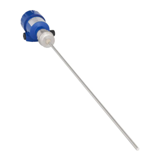
Rod and cable probe tdr sensor for continuous level and interface measurement of liquids
Hide thumbs
Also See for NivoGuide 8100:
- Instruction manual (76 pages) ,
- Quick setup manual (17 pages)

Related Manuals for UWT NivoGuide 8100


Summary of Contents for UWT NivoGuide 8100
- Page 1 NivoGuide® 8100 Two-wire 4 … 20 mA/HART Rod and cable probe TDR sensor for continuous level and interface measurement of liquids Quick setup guide Document ID: 61266...
-
Page 2: Table Of Contents
This quick setup guide enables quick setup and commissioning of your instrument. operating instructions as well as in the Safety Manual for instruments Operating instructions NivoGuide 8100 - 4 … 20 mA/HART - Two-wire - Rod and cable probe: Document-ID 58878 Editing status of the quick setup guide: 2019-02-12... -
Page 3: For Your Safety
During work on and with the device, the required personal protective equipment must always be worn. Appropriate use NivoGuide 8100 is a sensor for continuous level measurement. chapter "Product description". Operational reliability is ensured only if the instrument is properly manual as well as possible supplementary instructions. -
Page 4: Eu Conformity
NivoGuide® 8100 • Two-wire 4 … 20 mA/HART 1 For your safety EU conformity instrument with these directives. NAMUR recommendations NAMUR is the automation technology user association in the process industry in Germany. The published NAMUR recommendations are mendations: • NE 21 –... -
Page 5: Product Description
NivoGuide® 8100 • Two-wire 4 … 20 mA/HART 2 Product description Product description Type label use of the instrument: Fig. 1: Layout of the type label (example) Instrument type Product code Approvals (option) Power supply and signal output, electronics Protection rating Probe length (measurement accuracy optional) Process and ambient temperature, process pressure Material wetted parts... -
Page 6: Mounting
Mounting instructions Installation position Mount NivoGuide 8100 in such a way that the distance to vessel installations or to the vessel wall is at least 300 mm (12 in). In non- metallic vessels, the distance to the vessel wall should be at least 500 mm (19.7 in). - Page 7 NivoGuide® 8100 • Two-wire 4 … 20 mA/HART 3 Mounting When mounting rod or cable probes in vessels without metal walls, Fig. 3: Mounting in non-metallic vessel Flange Metal sheet Mounting socket If this is not possible, use short sockets with small diameter. Higher sockets or sockets with a bigger diameter can generally be used.
- Page 8 NivoGuide® 8100 • Two-wire 4 … 20 mA/HART 3 Mounting vessel top. Unfavourable mounting...
-
Page 9: Connecting To Power Supply
NivoGuide® 8100 • Two-wire 4 … 20 mA/HART 4 Connecting to power supply Connecting to power supply Connecting Connection technology The voltage supply and signal output are connected via the spring- loaded terminals in the housing. Connection to the display and adjustment module or to the interface adapter is carried out via contact pins in the housing. -
Page 10: Wiring Plan, Single Chamber Housing
NivoGuide® 8100 • Two-wire 4 … 20 mA/HART 4 Connecting to power supply 8. Connect the screen to the internal ground terminal, connect the 9. Tighten the compression nut of the cable entry gland. The seal ring must completely encircle the cable 10. - Page 11 NivoGuide® 8100 • Two-wire 4 … 20 mA/HART 4 Connecting to power supply Connection compartment 4...20mA Display 6 7 8 Fig. 8: Connection compartment - double chamber housing Voltage supply, signal output For display and adjustment module or interface adapter For external display and adjustment unit Ground terminal for connection of the cable screening...
-
Page 12: Set Up With The Display And Adjustment Module
NivoGuide® 8100 • Two-wire 4 … 20 mA/HART 5 Set up with the display and adjustment module Set up with the display and adjustment module Insert display and adjustment module The display and adjustment module can be inserted into the sensor ent positions - each displaced by 90°. -
Page 13: Parameter Adjustment - Quick Setup
NivoGuide® 8100 • Two-wire 4 … 20 mA/HART 5 Set up with the display and adjustment module Fig. 10: Installing the display and adjustment module in the double chamber housing In the electronics compartment In the connection compartment Note: module for continuous measured value indication, a higher lid with an inspection glass is required. - Page 14 NivoGuide® 8100 • Two-wire 4 … 20 mA/HART 5 Set up with the display and adjustment module Application In this menu item, you can select the application. You can choose between level measurement and interface measurement. You can also choose between measurement in a vessel or in a bypass or standpipe.
- Page 15 NivoGuide® 8100 • Two-wire 4 … 20 mA/HART 5 Set up with the display and adjustment module Max. adjustment - Interface To do this, enter the percentage value and the corresponding dis- tance value in m for the full vessel. Min.
-
Page 16: Supplement
NivoGuide® 8100 • Two-wire 4 … 20 mA/HART 6 Supplement Supplement Technical data Note for approved instruments The technical data in the respective safety instructions are valid for approved instruments (e.g. with conditions or the voltage supply. Electromechanical data - version IP 66/IP 67 and IP 66/IP 68; 0.2 bar Cable entry ½... - Page 17 Subject to change without prior notice Technical support Please contact your local sales partner (address at www.uwt.de). Otherwise please contact us: UWT GmbH Phone +49 831 57123-0 Fax +49 831 76879 Westendstraße 5...
Need help?
Do you have a question about the NivoGuide 8100 and is the answer not in the manual?
Questions and answers