Table of Contents
Advertisement
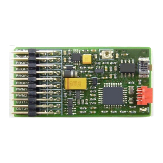
Digital Multifunctional RC-Soundmodule
TBS Mini V2
Important notes about changes on the NEW TBS Mini V2
!!! MUST BE READ !!!
Volume
New connector:
External amplifier
Unchanged connectors
(same as old TBS Mini V1)
max. 6V !!!
Most important: Receiver power supply must be 4V to
This range is covered by most BEC receiver power supply.
New sound memory
- 16x larger → Enough for 24,8 minutes of sound
- „Erasing Flash" lasts about 45s
- Filling the new sound memory completely takes about 45 minutes !
The NEW TBS Flash V4 software must be used for programming this TBS Mini
3W digital audio amplifier on board
4Ohm and 8Ohm speakers can be used
External amplifier connector on top → see picture above.
All other connectors remain unchanged and are located one position lower than on the old TBS
Mini. Please see the TBS Mini V2 manual page 4 for all details.
The new connector allows direct usage of most 3
rd
party amplifiers.
Hardware volume controller located on the Mini. Internal and ext. amplifier volume is set by this
controller. In parallel it is still possible changing the volume by the transmitter (if the Mini
parameters settings are accordingly)
External amplifier and a speaker connected directly to the TBS Mini can be used in parallel
Very important:
Connecting any 3
rd
party amplifier is FULLY on your OWN RISK regarding ANY damages
There will be no support for any 3
rd
party amplifier.
TBS Mini V2, 11/2018
www.benedini.de
Page 1 of 13
Advertisement
Table of Contents

Related Manuals for Benedini TBS Mini V2


Summary of Contents for Benedini TBS Mini V2
- Page 1 External amplifier connector on top → see picture above. All other connectors remain unchanged and are located one position lower than on the old TBS Mini. Please see the TBS Mini V2 manual page 4 for all details. The new connector allows direct usage of most 3 party amplifiers.
- Page 2 O OpenPanzer Configuration -> see www.openpanzer.org Loaded sound: _________________________________________________ Flashing output: O None O Out1 O Out2 O Out3 O Out4 Comment: ________________________________________________________ ________________________________________________________ TBS Flash version: O Version 1 O Version 4 TBS Mini V2, 11/2018 www.benedini.de Page 2 of 13...
- Page 3 Totally programmable by the free of charge software “TBS Flash”: - You can load your own sounds or any of the Benedini sounds available at www.benedini.de Firmware update! This means you have always the latest software at you unit.
- Page 4 Volume is set on the TBS Mini. If a common servo cable is used for making the audio connection, is signal and BROWN is ground. DO NOT CONNECT A SPEAKER TO THIS PORT !!! TBS Mini External amplifier Free Audio Signal Audio In (red) Groung (brown) TBS Mini V2, 11/2018 www.benedini.de Page 4 of 13...
- Page 5 PLUS is available at the centre contacts of each connector → See connection picture above. Out 10 is located at the signal pin of PWM1 (upper pin) Out 11 is located at the signal pin of PWM2 (upper pin) TBS Mini V2, 11/2018 www.benedini.de Page 5 of 13...
-
Page 6: Installation Schematic
Main Battery ESC + BEC Receiver TBS Mini V2 Speed Optional Control optional Universal switching outputs Orange OUT 2 OUT 1 Black Orange OUT 4 OUT 3 Black Resistors for LEDs TBS Mini V2, 11/2018 www.benedini.de Page 6 of 13... -
Page 7: First Setup
TX by two solder bridges at the rear side of the encoder pcb: BOTH bridges Total resistance Connect to spare prop. trigger switch open app. 22 KOhm Channel of your TX. closed app. 5 KOhm TBS Mini V2, 11/2018 www.benedini.de Page 7 of 13... - Page 8 8) After teaching all positions the sound unit beeps 3x and is back in normal operation mode. Hint: If you are using the resistor network shown above instead of the encoder, each rotary switch position is represented by one of the push buttons. TBS Mini V2, 11/2018 www.benedini.de Page 8 of 13...
- Page 9 Advantage of this way of using the direct mode is, that you can choose the sounds you want to – have during teaching. TBS Mini V2, 11/2018 www.benedini.de Page 9 of 13...
- Page 10 6. Flick the 3-position control switch at the transmitter and set it back to center -> A short sequence of full speed is played. 7. Sound unit returns to normal operation mode → Green LED is blinking fast TBS Mini V2, 11/2018 www.benedini.de Page 10 of 13...
-
Page 11: Auto Start
-> 12- Key coder Note: This will NOT work for changes from Autostart to 2-key or 12-key coder mode, due to a missing sound list definition. Changes vice versa are possible. TBS Mini V2, 11/2018 www.benedini.de Page 11 of 13... -
Page 12: Safety Aspects
Amplifier, Speakers, etc. will be operated within the parameters contained therein. www.benedini.de accepts no liability for any damage to any Sound Module if it is determined that the damage has been caused by either non adherence to the instructions or due to any malfunction by any cause or reason whatsoever within the model or its equipment and thereby outside of the control of www.benedini.de. - Page 13 Standard wiring of TBS Mini in “Autostart” control mode, together with 1x40W amplifier Attention: !!! Picture shows the “old” TBS Mini !!! TBS Mini V2, 11/2018 www.benedini.de Page 13 of 13...
Need help?
Do you have a question about the TBS Mini V2 and is the answer not in the manual?
Questions and answers