Table of Contents
Advertisement
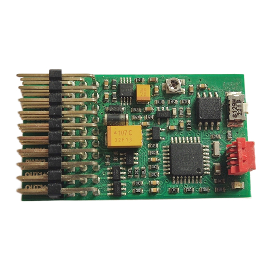
Digital Multifunction Sound Unit
*** FREE OF CHARGE sound libraries available at www.benedini.de ***
Content
1.
2.
2.1.
3.
3.1.
3.1.1
3.2.
3.3.
3.4.
4.
5.
Configuration of the sound unit by the optional USB programming cable and a PC
6.
The Control Mode set on this Sound unit on delivery:
O Encoder (Prop3)
O Indirect Sound Selection (Prop3) O Autostart
Loaded sound set: ________________________
Flashing output:
O None
TBS Mini
TBS Mini
O Direct Sound Selection (Prop2)
O Out1
www.benedini.de
O Out2
Page 1 of 11
Advertisement
Table of Contents

Subscribe to Our Youtube Channel
Related Manuals for Benedini TBS Mini


Summary of Contents for Benedini TBS Mini
-
Page 1: Table Of Contents
Digital Multifunction Sound Unit TBS Mini *** FREE OF CHARGE sound libraries available at www.benedini.de *** Content Features Connections 2.1. Installation schematic Control modes 3.1. Controlling the sound unit by the 12-positon “encoder” (12-Key coder) 3.1.1 Push button encoder circuit 3.1.2. -
Page 2: Features
- Firmware update! This means you have always the latest software at you unit. - FREE OF CHARGE sound libraries available at www.benedini.de The TBS Mini sound unit can be fully configured by the optional USB programming cable and a PC. Please see the separate programming manual. -
Page 3: Connections
(negative) Speaker connection: If a speaker is connected directly to the TBS Mini, make sure to use the Speaker Plus and Speaker Minus pins (upper two pins). You must NOT use the Ground pin at the speaker connector! Use only an 8 Ohm speaker. -
Page 4: Installation Schematic
All switching outputs (Out1-6) can be configured to different modes (switching, latching, flashing) and can be routed to different sounds for simultaneous action. Most common is using them for gun muzzle flashing. High power LEDs, including pre-wired cable sets, are available. TBS Mini www.benedini.de Page 4 of 11... -
Page 5: Control Modes
3. Control modes There are several control modes possible, using various TX switch functions and the appropriate Prop’X’ control inputs, with the TBS Mini Sound Unit also set to interpret the signals correctly. Encoder. Using a 12 position encoder, or multi-switch panel. -
Page 6: Push Button Encoder Circuit
8) After teaching all positions the sound unit will beep 3 times and will revert back into normal operation mode. If you are using the switch/resistor network shown above instead of the encoder, each rotary switch position is represented by one of the push buttons. TBS Mini www.benedini.de Page 6 of 11... -
Page 7: Direct Sound Selection
You do not need to ‘teach’ the Sound unit anything for this mode. The 3pos switch RX channel must be connected to Prop2 input of the TBS Mini Prop2 input. The mode set for Prop2 in the TBS Mini must be set to “Function ½” by the TBS Flash software. The two switch positions will play: 1) The engine Start or Shutdown sound (toggles) and 2) The first sound file in the Additional Sounds list. -
Page 8: Indirect Sound Selection "2-Key Coder
This mode can utilise a 3pos switch as an ‘encoder’ so that you can select ANY of the Additional Sound Files to play. The 3pos switch RX channel must be connected to Prop3 input of the TBS Mini. The mode set for Prop3 in the TBS Mini must be set to “1 Coder 2 Key”... -
Page 9: Autostart
If you want to switch from autostart to another control mode you need to program a control channel by using TBflash and the optional programming cable! 5. Connecting an external amplifier If you want to connect an external amplifier, other than a Benedini one, please follow this schematic: Watch the ground connection !!!! -
Page 10: Technical Data
PC Please see the separate manual for the configuration software called “TBS Flash”. The manual as well as the software is available free of charge at www.benedini.de. Note: The sound unit needs to be powered from the receiver power while being used with a PC. It is NOT powered by the USB cable! 7. - Page 11 Standardwiring of TBS Mini in “Autostart” control mode, together with 2x40W amplifier TBS Mini www.benedini.de Page 11 of 11...
Need help?
Do you have a question about the TBS Mini and is the answer not in the manual?
Questions and answers