Table of Contents
Advertisement
Quick Links
Advertisement
Table of Contents

Related Manuals for Micromeritics FlowPrep 060

Summary of Contents for Micromeritics FlowPrep 060
- Page 1 FlowPrep 060 Operator’s Manual 060-42803-01 Nov 2010...
- Page 2 © Micromeritics Instrument Corporation 2002-2010. All rights reserved. Printed in the U.S.A.
- Page 3 MICROMERITICS shall not be liable for consequential or other type damages resulting from the use of any of its products other than the liability stated above. This warranty is in lieu of all other warranties, express or implied, including, but not limited to, the implied warranties of merchantability or fitness for use.
-
Page 5: Table Of Contents
FlowPrep 060 Table of Contents INDEX GENERAL INFORMATION Description ..............1-1 Conventions . - Page 6 Table of Contents FlowPrep 060 Ordering Information INDEX May 2010...
-
Page 7: General Information
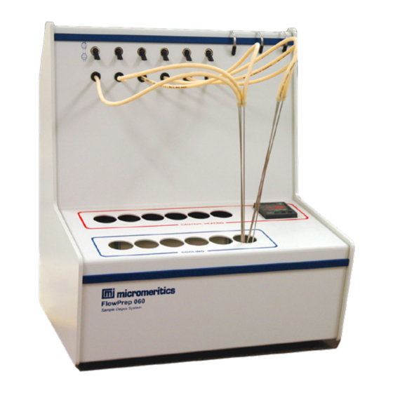
1. GENERAL INFORMATION Description The FlowPrep 060 Degasser prepares samples for adsorption analysis. It uses flowing gas passed over a heated sample to remove moisture and other contaminants. The degasser has six heating stations for degassing samples and six cooling stations. The desired degassing temper- ature is easily set on the temperature controller pad located on the front of the instrument. -
Page 8: Conventions
Conventions FlowPrep 060 Conventions This manual uses the symbols shown below to identify notes of importance, warnings, and cautions. Notes contain important information pertinent to the subject matter. Warnings contain information that help you prevent actions that may cause personal injury. -
Page 9: Specifications
FlowPrep 060 Specifications Specifications The following table gives the specifications of the FlowPrep 060 Degasser. Table 1-1. Specifications Characteristic Specification Sample Tubes Up to 3.0-cm (1.18-in.) OD Heating Block Temperature: 10 ºC above ambient to 400 ºC Temperature Accuracy: ± 10... -
Page 11: Installation
If equipment is damaged or lost in transit, you are required to make note of the damage or loss on the freight bill. The freight carrier, not Micromeritics, is responsible for all damage or loss occurring during shipment. If you discover damage or loss of equipment during shipment, report the condition to the carrier immediately. -
Page 12: Selecting The Input Power
Selecting the Input Power FlowPrep 060 Selecting the Input Power All instruments leave the factory set for 120 VAC and with the line fuse removed. The correct setting of the universal power entrance must be checked and the appropriate fuse(s) installed before the degasser can be operated. - Page 13 FlowPrep 060 Selecting the Input Power Power Source Fuse 100-120 VAC 2.5 Amp, slow blow (requires one) 200-240 VAC 1.25 Amp, slow-blow, Type T Time lag, (requires two) 6. Position the fuse block so that the side containing the fuse(s) is facing the power module and insert it into the connector.
-
Page 14: Rear Panel Connections
Rear Panel Connections FlowPrep 060 Rear Panel Connections 1. Insert one end of the power cord into the input power connector at the rear of the degasser and the other end into the appropriate power source. When the FlowPrep leaves the factory, stabilizing tubes are placed in heating stations 1 and 6 to prevent the heater block from shifting during shipment. - Page 15 FlowPrep 060 Rear Panel Connections 6. Attach the other end of the copper tubing to the fitting on the back of the degasser. Copper Tubing Gas Fitting 7. Open the gas bottle shut-off valve. 8. Use the regulator pressure control knob to adjust the pressure. The following table shows pressures and their resulting flow rates (tested with helium and nitrogen).
-
Page 16: Attaching The Gas Delivery Tubes
Attaching the Gas Delivery Tubes FlowPrep 060 Attaching the Gas Delivery Tubes Six gas delivery tubes are included in the accessories kit. Attach one to each flexible tube by pressing the flexible tube over the gas delivery tube. Make sure that the flexible tube com- pletely covers the ferrule at the end of the gas delivery tube. -
Page 17: Operation And Sample Preparation
FlowPrep 060 Operation 3. OPERATION AND SAMPLE PREPARATION Operation Front Panel Controls Flow Control Valves Temperature Controller Temperature Controller The temperature controller displays the current temperature of the heating stations and enables you to change the temperature set point. Refer to... -
Page 18: Rear Panel Controls
Operation FlowPrep 060 Rear Panel Controls Gas Port On/Off Switch On/Off Switch Place the switch in the up position ( | ) to turn on the degasser, and in the down position (0) to turn off the degasser. Gas Port The gas port is used to connect the gas supply to the degasser. -
Page 19: Controlling The Temperature Of Heating Stations
FlowPrep 060 Operation Controlling the Temperature of Heating Stations The temperature controller, shown below, enables you to specify the temperature of the heat- ing stations and displays the current temperature. Lights when power is being applied to heating stations Displays current temperature... -
Page 20: Sample Preparation
Sample Preparation FlowPrep 060 Sample Preparation Cleaning Sample Tubes Sample tubes must be clean in order to obtain accurate analysis results. Clean the tubes in an ultrasonic cleaning unit as follows. The materials required for cleaning and weighing samples are: •... - Page 21 FlowPrep 060 Sample Preparation 5. Using either rubber gloves or a lint-free cloth (but not bare hands), remove the sample tube from the bowl. 6. Clean the interior of the sample tube with the brush supplied in the accessories kit.
-
Page 22: Weighing The Sample
Sample Preparation FlowPrep 060 10. After degassing the empty sample tube and stopper, weigh it while it still contains gas. To get an accurate weight of a degassed sample, the gas in both the empty sample tube and in the tube when it contains the sample must be the same. - Page 23 FlowPrep 060 Sample Preparation 6. Pour the sample from the sample weighing container into the sample tube using a funnel. 7. Insert the sample tube stopper. 8. Weigh the sample tube, sample, and rubber stopper. Record the weight as sample plus sample tube weight.
-
Page 24: Inserting And Removing Heating Station Adapters
Sample Preparation FlowPrep 060 Inserting and Removing Heating Station Adapters Heating station adapters are included in the FlowPrep accessories kit for use with sample tubes. There are three models of heating station adapters. Use the appropriate model as shown in Table 2-1 and follow the instructions in this chapter for removing and inserting adapters. - Page 25 FlowPrep 060 Sample Preparation Table 3-1. Heating Station Adapters Analyzer Model Sample Tubes Adapter Model TriStar ASAP Series 1/4-, 3/8-, or 1/2-in. Stem, P/N: 065-25815-00 1.2-in. (30-mm) Bulb Gemini (Bulb Tube) P/N: 065-25811-00 3/8-in. Stem, 3/4-in. (19 mm) Bulb Gemini (Straight-Wall Tube) 3/8-in.
-
Page 26: Tristar And Asap Series Sample Tubes
Sample Preparation FlowPrep 060 TriStar and ASAP Series Sample Tubes Adapters are included as a standard accessory with the FlowPrep. Additional adapters may be ordered if needed (refer to Ordering Information, page 5-1.). Sample tubes and heating station adapters may be very hot. Wear the proper gloves and hold the sample tube by the upper part of its stem. -
Page 27: Removing Adapters
FlowPrep 060 Sample Preparation Removing Adapters Use station when moving sample tubes and heating station adapters to the cooling station. Sample tubes and heating station adapters may be very hot. Wear the proper gloves and hold the sample tube by the upper part of its stem. Hold the isothermal type of adapter by its handle. -
Page 28: Gemini Sample Tubes
Sample Preparation FlowPrep 060 Gemini Sample Tubes Adapters are included as a standard accessory with the FlowPrep. Additional adapters may be ordered if needed (refer to Ordering Information, page 5-1). Sample tubes and heating station adapters may be very hot. Wear the proper gloves and hold the sample tube by the upper part of its stem. -
Page 29: Degassing Samples
FlowPrep 060 Sample Preparation Degassing Samples 1. Place the degasser power switch in the ON ( | ) position. When the FlowPrep leaves the factory, stabilizing tubes are placed in heating stations 1 and 6 to prevent the heater block from shifting during shipment. Be sure to remove these tubes before turning on the FlowPrep. - Page 30 Sample Preparation FlowPrep 060 5. Remove the stopper from the sample tube and insert the gas delivery tube into the sample tube. The end of the gas delivery tube may be hot enough to cause burns if it was stored in a heating station instead of a cooling station.
- Page 31 FlowPrep 060 Sample Preparation 7. Using the appropriate adapter, place the sample tube in a vacant heating station. 8. Allow the sample to degas for the desired length of time. One to two hours is typical for many samples at temperatures above 200 ºC. To determine the optimum time, select the highest safe temperature for your sample, then degas it at intervals, determining the surface area after each interval.
- Page 32 Sample Preparation FlowPrep 060 10. Place the sample tube, with stopper and gas delivery tube still in place, in a cooling station. 11. The sample tube should be cool enough to handle after several minutes. Remove the tube from the cooling station. Hold the stopper loosely in the tube and slowly pull out the gas delivery tube.
- Page 33 FlowPrep 060 Sample Preparation 13. Place the flow control valve in the off position. 14. Wipe the gas delivery tube with a clean cloth to remove any particles of sample that may have adhered to it. Then, place the gas delivery tube in a cooling station until needed again.
-
Page 35: Troubleshooting And Maintenance
Troubleshooting 4. TROUBLESHOOTING AND MAINTENANCE The FlowPrep 060 requires very little maintenance to remain in top operating condition. The gas flow tubes should be wiped clean after each use and inspected weekly to ensure that they do not become clogged. This chapter contains instructions for inspecting and replacing gas flow tubes, as well as a troubleshooting chart and other maintenance procedures. - Page 36 Troubleshooting FlowPrep 060 What Happened What To Do Gas seems to be leaking The flow control valves were Keep the flow control valve from gas bottle. left in the open position when closed on all stations that are stations were not in use.
-
Page 37: Temperature Controller
FlowPrep 060 Temperature Controller Temperature Controller Error Messages The temperature controller performs self-diagnostics when the degasser is turned on and while operating. If an error occurs during self-diagnostics, one of the following error messages will be displayed. uuuu Cause: Temperature has risen substantially above temperature scale range or the temperature sensor has burned out (open circuit). -
Page 38: Maintenance
4-7). Gas delivery tubes and flexible tubing may be ordered in sets of six from Micromeritics. Refer to Ordering Information, page If gas flow is not present in other stations, refer to the following table. Table 4-2. Gas Flow Problems What To Do Gas pressure is set too low. -
Page 39: Cleaning And Replacing Gas Delivery Tubes
FlowPrep 060 Maintenance Cleaning and Replacing Gas Delivery Tubes Gas delivery tubes should be wiped with a lint-free cloth after each use to remove any particles of sample that may have adhered to the tube. If a gas delivery tube becomes clogged or damaged, it should be replaced as follows: 1. -
Page 40: Replacing Flexible Tubing
Maintenance FlowPrep 060 Replacing Flexible Tubing If the flexible tubing becomes damaged, replace it as follows. 1. Close the appropriate gas flow valve if it is open. 2. Remove the flexible tubing from the gas delivery tube. 3. Remove the top rear panel by removing the six screws that secure it. -
Page 41: Connecting Or Replacing Valve Inlet Tubing
FlowPrep 060 Maintenance Connecting or Replacing Valve Inlet Tubing Flexible tubing connects the valves to the gas manifold inside the degasser. If there is no gas flow to a particular valve, the tubing could be disconnected. To check the tubing: 1. - Page 43 FlowPrep 060 Ordering Information 5. Ordering Information The FlowPrep 060 System components and accessories can be ordered using one of the fol- lowing methods: • Call our Customer Service Department at (770) 662-3636 • Access our web site at www.micromeritics.com •...
- Page 45 Flow Prep 060 Index INDEX Accessories, ordering, Maintenance, Adapter See Heating Station Adapters Notes, defined, Cautions, defined, Conventions, operator’s manual, Operator’s manual, conventions, Ordering information, Equipment, returning, Error messages, Parts, ordering, Flow control valve, FlowPrep Rear panel description, connections, front panel controls, controls, ordering components and accessories, rear panel controls,...
- Page 46 Index Flow Prep 060 Valve inlet tubing, replacing, Warnings, defined, Voltage selecting, Index-2 May 2010...
Need help?
Do you have a question about the FlowPrep 060 and is the answer not in the manual?
Questions and answers