Sign In
Upload
Download
Table of Contents
Contents
Add to my manuals
Delete from my manuals
Share
URL of this page:
HTML Link:
Bookmark this page
Add
Manual will be automatically added to "My Manuals"
Print this page
×
Bookmark added
×
Added to my manuals
Manuals
Brands
RGBlink Manuals
Digital Camera
RGB12X-PTZ-WH
User manual
RGBlink RGB12X-PTZ-WH User Manual
Ptz camera
Hide thumbs
1
Table Of Contents
2
3
4
5
6
7
8
9
10
11
12
13
14
15
16
17
18
19
20
21
22
23
24
25
26
27
28
29
30
31
32
33
34
35
36
37
38
39
40
41
42
43
44
45
46
47
48
49
50
51
52
53
page
of
53
Go
/
53
Contents
Table of Contents
Troubleshooting
Bookmarks
Table of Contents
Table of Contents
Declarations
Fcc/Warranty
Operators Safety Summary
Installation Safety Summary
Chapter 1 Your Product
In the Box
Product Overview
Product Model
Dimension
Main Features
Chapter 2 Install Your Product
Camera Interface Explanation
External Interface
Bottom Dial Switch
RS-232 Interface
Bracket Mount
Chapter 3 Use Your Product
Video Output
Power on Initial Configuration
Remote Controller
Keys Instruction
Applications
Menu Setting
Main Menu
System Setting
Camera Setting
P/T/Z
Video Format
Version
Restore Default
Network Connection
Connecting Mode
IE Log in
Web Client
Preview
Configuration
Audio Configuration
Video Configuration
Network Configuration
System Configuration
Logout
Chapter 4 Ordering Codes
Product
Chapter 5 Support
Contact Us
Camera Maintenance and Troubleshooting
Camera Maintenance
Troubleshooting
Chapter 5 Appendix
VISCA Protocol List
Camera Return Command
Camera Control Command
Inquiry Command
Pelco-D Protocol Command List
Pelco-P Protocol Command List
Terms & Definitions
Revision History
Advertisement
Quick Links
1
Camera Interface Explanation
2
Remote Controller
3
Network Connection
4
Network Configuration
Download this manual
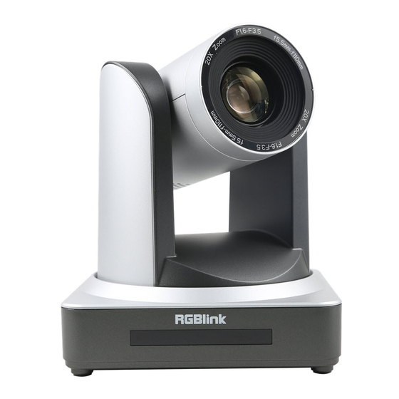
PTZ Camera
User Manual
Article No: RGB-RD-UM-PTZ E001
Version: V1.0
Table of
Contents
Previous
Page
Next
Page
1
2
3
4
5
Advertisement
Table of Contents
Need help?
Do you have a question about the RGB12X-PTZ-WH and is the answer not in the manual?
Ask a question
Questions and answers
Related Manuals for RGBlink RGB12X-PTZ-WH
Digital Camera RGBlink RGB20X-PTZ-WH User Manual
Ptz camera (53 pages)
Digital Camera RGBlink RGB20X/30X-PNDI-WH User Manual
Ndi camera (55 pages)
Digital Camera RGBlink RGB3X-EPTZ-BK User Manual
Eptz educational trackingcamera (40 pages)
Digital Camera RGBlink PTZ AI User Manual
Tracking camera (49 pages)
Digital Camera RGBlink mini+ Installation Precautions
Ptz camera control (9 pages)
This manual is also suitable for:
Rgb20x-ptz-wh
Table of Contents
Print
Rename the bookmark
Delete bookmark?
Delete from my manuals?
Login
Sign In
OR
Sign in with Facebook
Sign in with Google
Upload manual
Upload from disk
Upload from URL


Need help?
Do you have a question about the RGB12X-PTZ-WH and is the answer not in the manual?
Questions and answers